Ford Explorer: Electronic Engine Controls - 2.3L EcoBoost (201kW/273PS) / Removal and Installation - Heated Oxygen Sensor (HO2S)
Special Tool(s) / General Equipment
.jpg) |
303-476
(T94P-9472-A)
Socket, Exhaust Gas Oxygen Sensor TKIT-1994-LM/M TKIT-1994-F TKIT-1994-FLM/FM |
Materials
| Name | Specification |
|---|---|
| Motorcraft® High Temperature Nickel Anti-Seize Lubricant XL-2 |
- |
| Motorcraft® Penetrating and Lock Lubricant XL-1 |
- |
| Motorcraft® Silicone Brake Caliper Grease and Dielectric Compound XG-3-A |
ESE-M1C171-A |
Removal
NOTE: Removal steps in this procedure may contain installation details.
-
With the vehicle in NEUTRAL, position it on a hoist.
Refer to: Jacking and Lifting - Overview (100-02 Jacking and Lifting, Description and Operation).
-
NOTICE: Do not pull the engine appearance cover forward or sideways to remove. Failure to press straight upward on the underside of the cover at the attachment points may result in damage to the cover or engine components.
-
Remove the engine appearance cover nut.
-
Place your hand under the engine appearance cover at
each grommet location and pull straight up to release each grommet from
the studs.
-
After all of the grommets have been released from the studs, remove the appearance cover from the engine.
-
Remove the engine appearance cover nut.
.jpg) |
-
Disconnect the electrical connector. Apply penetrating oil to sensor, using the special tool remove the HO2S.
Use Special Service Tool: 303-476 (T94P-9472-A) Socket, Exhaust Gas Oxygen Sensor.
Use Suggested Tool: 303-476 (T94P-9472-A) Socket, Exhaust Gas Oxygen Sensor. Tool shown or a commercially available equivalent can be used.
Material: Motorcraft® Penetrating and Lock Lubricant / XL-1
.jpg) |
Installation
-
To install, reverse the removal procedure.
-
Apply anti-seize to thread of sensor, using special tool install the HO2S. Connect the electrical connector.
Use Special Service Tool: 303-476 (T94P-9472-A) Socket, Exhaust Gas Oxygen Sensor.
Material: Motorcraft® High Temperature Nickel Anti-Seize Lubricant / XL-2
Torque: 35 lb.ft (48 Nm)
.jpg) |
-
-
NOTE: Lubricating the grommets with silicone grease will aid in the installation of the engine appearance cover, and any future removal and installation of the cover.
Lubricate each grommet with silicone grease.
Material: Motorcraft® Silicone Brake Caliper Grease and Dielectric Compound / XG-3-A (ESE-M1C171-A)
-
Position the engine appearance cover onto engine with the grommets aligned with the studs.
-
Press down on the engine appearance cover at each grommet location to attach the grommets onto the studs.
-
Install the engine appearance cover nut.
Torque: 44 lb.in (5 Nm)
-
If the engine appearance cover stud bolt is loosened
or removed, it must be installed/tightened into the valve cover.
Torque: 62 lb.in (7 Nm)
-
.jpg) |
 Removal and Installation - Fuel Rail Pressure (FRP) Sensor
Materials
Name
Specification
Motorcraft® Silicone Brake Caliper Grease and Dielectric CompoundXG-3-A
ESE-M1C171-A
Removal
NOTE:
Removal steps in this procedure may conta..
 Removal and Installation - Intake Air Temperature (IAT) Sensor
Removal
NOTE:
Removal steps in this procedure may contain installation details.
Disconnect the IAT electrical connector.
Remove the IAT sensor...
Other information:
Ford Explorer 2020-2025 Service Manual: Description and Operation - D Clutch
Overview Item Description 1 SSD 2 D clutch control valve 3 Clutch gain control valve 4 D clutch apply circuit 5 D clutch piston 6 D clutch assembly 7 Planetary carrier No...
Ford Explorer 2020-2025 Owners Manual: Direction Indicators
Switching the Direction Indicators On and Off Push the lever up or down to switch the direction indicators on. Note: Tap the lever up or down to make the direction indicators flash three times. Set the lever to the middle position to switch the direction indicators off...
Categories
- Manuals Home
- 6th Generation Explorer Owners Manual
- 6th Generation Explorer Service Manual
- Automatic Transmission - 10-Speed Automatic Transmission – 10R60
- Removal and Installation - Liftgate Trim Panel
- General Procedures - Transmission Fluid Drain and Refill
- New on site
- Most important about car
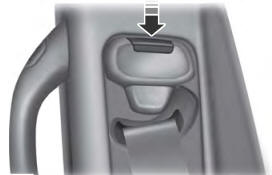
Seatbelt Height Adjustment
WARNING: Position the seatbelt height adjuster so that the seatbelt rests across the middle of your shoulder. Failure to adjust the seatbelt correctly could reduce its effectiveness and increase the risk of injury in a crash.

