Ford Explorer: Engine - 2.3L EcoBoost (201kW/273PS) / Removal and Installation - Engine Mount LH
Special Tool(s) /
General Equipment
.jpg) |
303-050
(T70P-6000)
Lifting Bracket, Engine |
.jpg) |
303-F072
Support Bar, Engine |
| Oil Drain Equipment |
| Cable Ties |
Materials
| Name |
Specification |
Motorcraft® Silicone Brake Caliper Grease and Dielectric Compound
XG-3-A |
ESE-M1C171-A
|
Removal
-
With the vehicle in NEUTRAL, position it on a hoist.
Refer to: Jacking and Lifting - Overview (100-02 Jacking and Lifting, Description and Operation).
-
Using a holding device, hold the steering wheel.
-
Remove the bolts and the suspension support bar.
-
NOTICE:
Do not pull the engine appearance cover forward or
sideways to remove. Failure to press straight upward on the underside of
the cover at the attachment points may result in damage to the cover or
engine components.
-
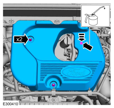
Remove the engine appearance cover nuts.
-
Place your hand under the engine appearance cover at
the grommet location and push straight up to release the grommet from
the stud.
-
After the grommet has been released from the stud, remove the appearance cover from the engine.
-
Drain the cooling system.
Refer to: Engine Cooling System Draining, Vacuum Filling and Bleeding (303-03A Engine Cooling - 2.3L EcoBoost (201kW/273PS), General Procedures).
-
Remove the cowl panel.
Refer to: Cowl Panel (501-02 Front End Body Panels, Removal and Installation).
-
-
Remove the bolt and disconnect the steering shaft.
-
If equipped, remove the retainers and the upper radiator panel.
-
Using cable ties or mechanics wire through the upper location holes, to support the cooling module.
Use the General Equipment: Cable Ties
-
Loosen the CAC tube clamp and position aside.
-
Remove the bolts (Enhanced Hexalobular or TORX PLUS ®
Acument Intellectual Properties, LLC as the owner) and the shield.
-
Detach the retainers, remove the bolt and position the ground wire aside.
-
Using the ground wire bolt, install the special tool.
Install Special Service Tool: 303-050
(T70P-6000)
Lifting Bracket, Engine.
-
NOTE:
Make sure to use the round feet on the shock towers or damage may occur.
Install Special Service Tool: 303-F072
Support Bar, Engine.
-
Remove the LH and RH front wheels and tires.
Refer to: Wheel and Tire (204-04A Wheels and Tires, Removal and Installation).
-
NOTICE:
Use the internal or external hex-holding feature to
prevent the ball and stud from turning while removing or installing the
stabilizer bar link nuts. The link boot seal must not be allowed to
twist while tightening the link nuts or damage to the boot seal will
occur.
Remove the nut and position the LH sway bar link aside.
-
NOTICE:
Use the internal or external hex-holding feature to
prevent the ball and stud from turning while removing or installing the
stabilizer bar link nuts. The link boot seal must not be allowed to
twist while tightening the link nuts or damage to the boot seal will
occur.
Remove the nut and position the RH sway bar link aside.
-
-
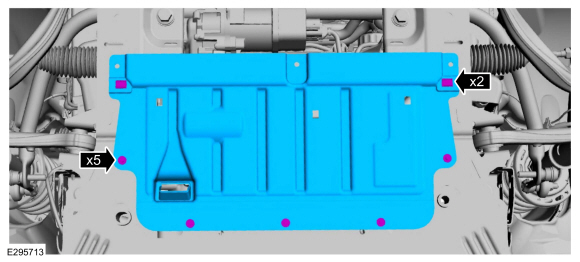
Remove pin-type retainer.
-
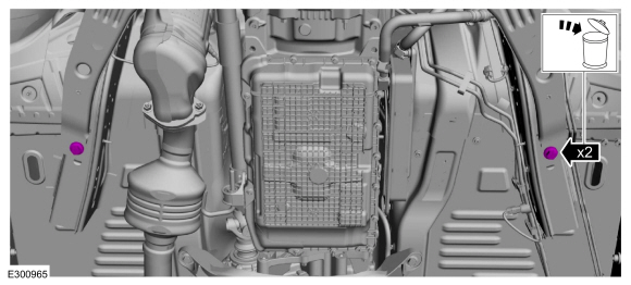
Remove the bolts and the underbody shield.
-
Remove the pin-type retainers, bolts and the rear underbody shield.
-
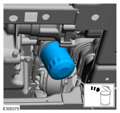
Remove and discard the engine oil filter.
Use the General Equipment: Oil Drain Equipment
-
-
Disconnect the coolant hose quick connect coupling and position aside.
-
Disconnect the auxiliary coolant pump wiring harness electrical connector and the retainer.
-
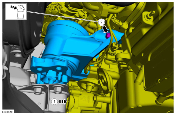
Remove the bolts and position the auxiliary coolant pump aside.
-
If equipped, remove the bolt and position the oil cooler aside.
-
If equipped, remove the steering shield pin-type retainers from the RH subframe.
-
Remove the splash shield pin-type retainer from the RH subframe.
-
Detach the HO2S wiring harness retainers from the RH subframe.
-
If equipped, remove the steering shield pin-type retainers from the LH subframe.
-
Remove the splash shield pin-type retainer from the LH subframe and position aside.
-
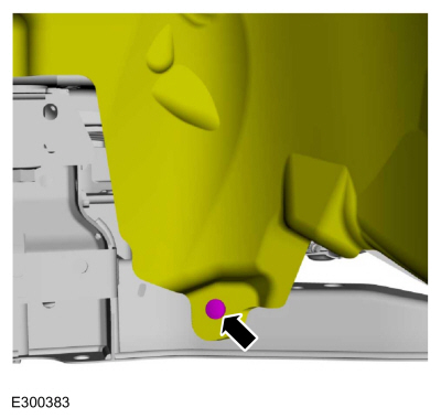
Remove and discard the LH engine mount bolts.
-
Remove and discard the LH engine mount bolts.
-
Remove the front radiator support bar bolts.
-
Detach the coolant tube retainers from the front of the subframe.
-
Remove the bolt and position the RH underbody shield aside.
-
Remove the bolt and position the LH underbody shield aside.
-
Mark the front subframe location.
-
Mark the rear subframe location.
-
Support the front and rear of the subframe with adjustable jack stands.
-
-
Remove the rear subframe bolts.
-
-
Remove the middle subframe bolts.
-
-
Remove the front subframe bolts.
-
With the aid of an assistant, lower the front jack stand
76.2 mm (3.0 in) and the rear jack stand 177.8 mm (7.0 in) evenly or
until engine mount stud clears the subframe.
-
-
With the aid of an assistant, position the engine
and transmission assembly to the right side to give clearance for engine
mount to clear the frame.
-
Remove and discard the engine mount bolt and remove the LH engine mount.
Installation
-
Clean the LH engine mount-to-frame mating surfaces of any dirt or foreign material prior to installation.
-
Clean the LH engine mount-to-engine block mating surfaces of any dirt or foreign material prior to installation.
-
-
With the aid of an assistant, position the engine
and trans assembly to the right side to give clearance for engine mount
to clear the frame.
-
Install the LH engine mount and the bolt finger tight.
-
With the aid of an assistant, raise the front and rear jack stand evenly.
-
Install the new front subframe bolts finger tight.
-
Install the new middle subframe bolts finger tight.
-
Install the new rear subframe bolts finger tight.
-
Install the new LH engine mount bolts finger tight.
-
Install the new RH engine mount bolts finger tight.
-
Tighten the LH engine mount bolts in sequence shown.
Torque:
Stage 1:
44 lb.ft (60 Nm)
Stage 2:
90°
-
Tighten the LH engine mount bolts in sequence shown.
Torque:
76 lb.ft (103 Nm)
-
Tighten the front subframe bolts.
Torque:
195 lb.ft (265 Nm)
-
Tighten the middle subframe bolts.
Torque:
195 lb.ft (265 Nm)
-
Tighten the rear subframe bolts.
Torque:
52 lb.ft (70 Nm)
-
Remove adjustable jack stands.
-
Position the LH underbody shield and install the bolt.
Torque:
22 lb.in (2.5 Nm)
-
Position the RH underbody shield and install the bolt.
Torque:
22 lb.in (2.5 Nm)
-
Attach the coolant tube retainers to the front of the subframe.
-
Install the front radiator support bar bolts.
Torque:
46 lb.ft (63 Nm)
-
Position the splash shield and install the pin-type retainer to the LH subframe.
-
Install the steering shield pin-type retainers to the LH subframe.
-
Attach the HO2S wiring harness retainers to the RH subframe.
-
Install the splash shield pin-type retainer to the RH subframe.
-
Install the steering shield pin-type retainers to the RH subframe.
-
If equipped, position the oil cooler and install the bolt.
Torque:
Stage 1:
17 lb.ft (22.5 Nm)
Stage 2:
75°
Stage 3:
Wait 2s
Stage 4:
15°
-
-
Position the auxiliary coolant pump and install the bolts.
Torque:
62 lb.in (7 Nm)
-
Connect the auxiliary coolant pump wiring harness electrical connector and the retainer.
-
Connect the coolant hose quick connect coupling.
-
Lubricate the new engine oil filter sealing surface with clean engine oil and install.
Torque:
Stage 1:
71 lb.in (8 Nm)
Stage 2:
180°
-
Install the rear underbody shield, bolts and the pin-type retainers.
Torque:
22 lb.in (2.5 Nm)
-
-
Install the underbody shield and the bolts.
Torque:
22 lb.in (2.5 Nm)
-
Install pin-type retainer.
-
NOTICE:
Use the internal or external hex-holding feature to
prevent the ball and stud from turning while removing or installing the
stabilizer bar link nuts. The link boot seal must not be allowed to
twist while tightening the link nuts or damage to the boot seal will
occur.
Position the RH sway bar link and install the new nut.
Torque:
129 lb.ft (175 Nm)
-
NOTICE:
Use the internal or external hex-holding feature to
prevent the ball and stud from turning while removing or installing the
stabilizer bar link nuts. The link boot seal must not be allowed to
twist while tightening the link nuts or damage to the boot seal will
occur.
Position the LH sway bar link and install the new nut.
Torque:
129 lb.ft (175 Nm)
-
Install the LH and RH front wheels and tires.
Refer to: Wheel and Tire (204-04A Wheels and Tires, Removal and Installation).
-
Remove Special Service Tool: 303-F072
Support Bar, Engine.
-
Remove Special Service Tool: 303-050
(T70P-6000)
Lifting Bracket, Engine.
-
Position the ground wire and install the bolt and attach the retainers.
Torque:
159 lb.in (18 Nm)
-
Install the shield and the bolts (Enhanced Hexalobular
or TORX PLUS ® Acument Intellectual Properties, LLC as the owner).
Torque:
18 lb.ft (25 Nm)
-
Position the CAC tube and tighten the clamp.
Torque:
44 lb.in (5 Nm)
-
Remove the radiator support cable ties or mechanics wire.
-
Install the upper radiator panel and the retainers.
-
Install the new steering shaft bolt.
Torque:
22 lb.ft (30 Nm)
-
Inspect and adjust the engine oil level.
Refer to: Specifications (303-01A Engine - 2.3L EcoBoost (201kW/273PS), Specifications).
-
Install the cowl panel.
Refer to: Cowl Panel (501-02 Front End Body Panels, Removal and Installation).
-
Fill the cooling system.
Refer to: Engine Cooling System Draining, Vacuum Filling and Bleeding (303-03A Engine Cooling - 2.3L EcoBoost (201kW/273PS), General Procedures).
-
-
NOTE:
Lubricating the grommets with silicone grease
will aid in the installation of the engine appearance cover, and any
future removal and installation of the cover.
Lubricate each grommet with silicone grease.
Material: Motorcraft® Silicone Brake Caliper Grease and Dielectric Compound
/ XG-3-A
(ESE-M1C171-A)
-
Position the engine appearance cover onto engine with the grommet aligned with the stud.
-
Press down on the engine appearance cover at the
grommet location to attach the grommet onto the stud and install the
nuts.
Torque:
44 lb.in (5 Nm)
-
Install the suspension support bar and the bolts.
Torque:
22 lb.ft (30 Nm)
-
Remove the holding device.
Special Tool(s) /
General Equipment
303-096
(T74P-6150-A)
Installer, Camshaft Front Oil SealTKIT-2009TC-F
303-1521Alignment Tool, Crankshaft Position SensorTKIT-2010C-FLM
303-16..
Special Tool(s) /
General Equipment
303-050
(T70P-6000)
Lifting Bracket, Engine
303-F072Support Bar, Engine
Cable Ties
Materials
Name
Specification
Motorcraft® Silic..
Other information:
System Diagram
Item
Description
1
SOBDMC
2
BCMC
3
PCM
4
Cabin Coolant Heater
5
Cabin heater coolant temperature sensor
6
Cabin heater coolant pump
7
Ambient Air Temperature (AAT) sensor
8
Engine Coolant Temperature (ECT) sensor
Network Message Chart - Module Network Input Messages - SOBDMC Cabin Coolant H..
Overview
The ABS
and stability control systems are comprised of the following subsystems
to assist the driver in maintaining control of the vehicle:
ABS
Curve control
Drive away release (EPB)
EBD
EPB control
ESC
Hill descent control
Hill start assist
Hydraulic fade compensation
RSC
Selectable drive modes
Supplementa..
Categories
Use the key blade to start your vehicle and unlock or lock the driver door from
outside your vehicle. The integrated keyhead transmitter functions as a programmed
ignition key that operates all the locks and starts your vehicle, as well as a remote
control.
read more
.jpg)
.jpg)
.jpg)
.jpg)
.jpg)
.jpg)
.jpg)
.jpg)
.jpg)
.jpg)
.jpg)
.jpg)
.jpg)
.jpg)
.jpg)
.jpg)
.jpg)
.jpg)
.jpg)
.jpg)
.jpg)
.jpg)
.jpg)
.jpg)
.jpg)
.jpg)
.jpg)
.jpg)
.jpg)
.jpg)
.jpg)
.jpg)
.jpg)
.jpg)
.jpg)
.jpg)
.jpg)
.jpg)
.jpg)
.jpg)
.jpg)
.jpg)
.jpg)
.jpg)
.jpg)
.jpg)
.jpg)
 Removal and Installation - Engine Front Cover
 Removal and Installation - Engine Mount RH