Ford Explorer: Engine - 2.3L EcoBoost (201kW/273PS) / Removal and Installation - Engine Front Cover
Special Tool(s) /
General Equipment
 |
303-096
(T74P-6150-A)
Installer, Camshaft Front Oil Seal
TKIT-2009TC-F |
.jpg) |
303-1521
Alignment Tool, Crankshaft Position Sensor
TKIT-2010C-FLM |
.jpg) |
303-1685
Alignment Tool, Camshaft |
 |
303-1689
Holding Tool, Crank Damper |
.jpg) |
303-409
(T92C-6700-CH)
Remover, Crankshaft Seal
TKIT-1992-FH/FMH/FLMH
TKIT-1993-LMH/MH |
 |
303-507
Timing Peg, Crankshaft TDC
TKIT-2001N-FLM
TKIT-2001N-ROW |
| Plastic Scraper |
| Oil Drain Equipment |
Materials
| Name |
Specification |
Motorcraft® High Performance Engine RTV Silicone
TA-357 |
WSE-M4G323-A6
|
Motorcraft® Silicone Gasket Remover
ZC-30-A |
-
|
Motorcraft® Metal Surface Prep Wipes
ZC-31-B |
-
|
Motorcraft® Silicone Brake Caliper Grease and Dielectric Compound
XG-3-A |
ESE-M1C171-A
|
Motorcraft® Metal Brake Parts Cleaner
PM-4-A, PM-4-B |
-
|
Removal
NOTICE:
Do not loosen or remove the crankshaft pulley bolt without
first installing the special tools as instructed in this procedure. The
crankshaft pulley and the crankshaft timing sprocket are not keyed to
the crankshaft. The crankshaft, the crankshaft sprocket and the pulley
are fitted together by friction. For that reason, the crankshaft
sprocket is also unfastened if the pulley bolt is loosened. Before any
repair requiring loosening or removal of the crankshaft pulley bolt, the
crankshaft and camshafts must be locked in place by the special service
tools, otherwise severe engine damage can occur.
NOTICE:
During engine repair procedures, cleanliness is extremely
important. All parts must be thoroughly cleaned and any foreign
material, including any material created while cleaning gasket surfaces,
that enters the oil passages, coolant passages or the oil pan, can
cause engine failure.
-
With the vehicle in NEUTRAL, position it on a hoist.
Refer to: Jacking and Lifting - Overview (100-02 Jacking and Lifting, Description and Operation).
-
Remove the bolts and the suspension support bar.
-
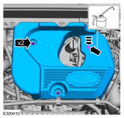
NOTICE:
Do not pull the engine appearance cover forward or
sideways to remove. Failure to press straight upward on the underside of
the cover at the attachment points may result in damage to the cover or
engine components.
-
Remove the engine appearance cover nuts.
-
Place your hand under the engine appearance cover at
the grommet location and push straight up to release the grommet from
the stud.
-
After the grommet has been released from the stud, remove the appearance cover from the engine.
-
Release the fuel system pressure.
Refer to: Fuel System Pressure Release (310-00A Fuel System - General Information - 2.3L EcoBoost (201kW/273PS), General Procedures).
-
Disconnect the battery ground cable.
Refer to: Battery Disconnect and Connect (414-01 Battery, Mounting and Cables, General Procedures).
-
Remove the following items:
-
Remove the air cleaner.
Refer to: Air Cleaner (303-12A Intake Air Distribution and Filtering - 2.3L EcoBoost (201kW/273PS), Removal and Installation).
-
Remove the air cleaner outlet.
Refer to: Air Cleaner Outlet Pipe (303-12A Intake Air Distribution and Filtering - 2.3L EcoBoost (201kW/273PS), Removal and Installation).
-
Remove the EVAP canister purge valve.
Refer to: Evaporative Emission Canister Purge Valve (303-13A Evaporative Emissions - 2.3L EcoBoost (201kW/273PS), Removal and Installation).
-
Disconnect the EVAP canister tube quick release coupling and the retainer and remove.
Refer to: Quick Release Coupling (310-00A Fuel System - General Information - 2.3L EcoBoost (201kW/273PS), General Procedures).
-
Remove the air cleaner inlet tube.
-
-
Detach the coolant hose retainer.
-
Detach the wiring harness retainer.
-
Remove the bolts and the air cleaner bracket.
-
Loosen the coolant pump pulley bolts.
-
Remove the following items:
-
Remove the accessory drive belt.
Refer to: Accessory Drive Belt (303-05A Accessory Drive - 2.3L EcoBoost (201kW/273PS), Removal and Installation).
-
Remove the accessory drive belt tensioner.
Refer to: Accessory Drive Belt Tensioner (303-05A Accessory Drive - 2.3L EcoBoost (201kW/273PS), Removal and Installation).
-
Remove the high-pressure fuel pump drive unit.
Refer to: High-Pressure Fuel Pump Drive Unit (303-04A Fuel Charging and Controls - 2.3L EcoBoost (201kW/273PS), Removal and Installation).
-
-
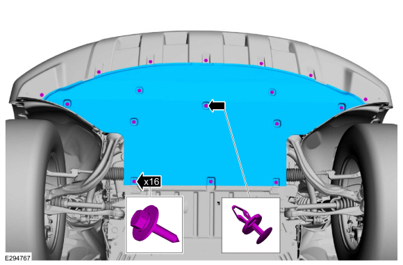
Remove pin-type retainer.
-
Remove the bolts and the underbody shield.
-
Remove the pin-type retainers, bolts and the rear underbody shield.
-
-
Disconnect the CKP sensor electrical connector.
-
Remove the bolts and the CKP sensor.
-
Turn the crankshaft clockwise until the No.1 piston is 45 degrees BTDC using the guide holes on the engine front cover and the crankshaft pulley.
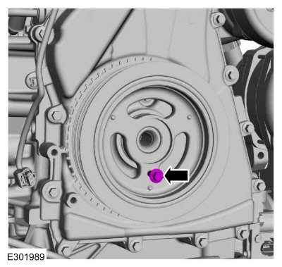
-
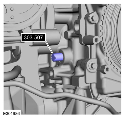
Remove the engine plug bolt.
-
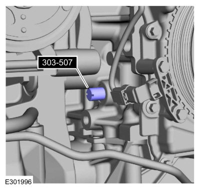
Install Special Service Tool: 303-507
Timing Peg, Crankshaft TDC.
-
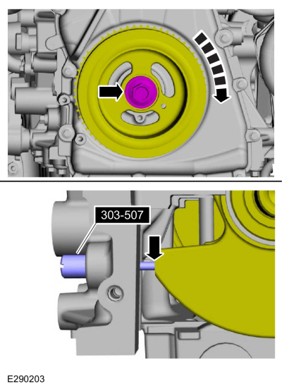
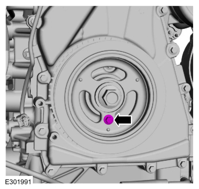
NOTE:
The Crankshaft TDC Timing Peg will contact the crankshaft and prevent it from turning past TDC. However, the crankshaft can still be rotated in the counterclockwise direction. The crankshaft must remain at the TDC position during the crankshaft pulley removal and installation.
NOTE:
The engine front cover is removed from graphic for clarity.
Rotate the crankshaft clockwise until the contacts the special tool.
Use Special Service Tool: 303-507
Timing Peg, Crankshaft TDC.
-
NOTICE:
The Camshaft Alignment Tool is for camshaft
alignment only. Using this tool to prevent engine rotation can result in
engine damage.
NOTE:
The camshaft timing slots are offset. If the Camshaft Alignment Tool cannot be installed, remove the TDC
Timing Peg and rotate the crankshaft three-fourths of a revolution
clockwise and repeat the previous 2 steps of this procedure.
Install Special Service Tool: 303-1685
Alignment Tool, Camshaft.
-
NOTICE:
The crankshaft must remain in the TDC
position during removal of the pulley bolt or damage to the engine can
occur. Therefore, the crankshaft pulley must be held in place with the
Crank Damper Holding Tool and the bolt should be removed using an air
impact wrench (1/2-in drive minimum).
-
Using the special tool, remove the bolt, washer and the crankshaft pulley.
Use Special Service Tool: 303-1689
Holding Tool, Crank Damper.
-
Install the old crankshaft pulley bolt.
-
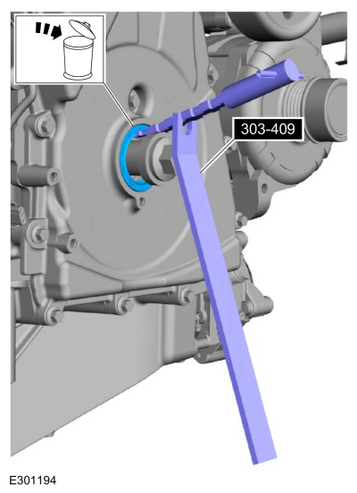
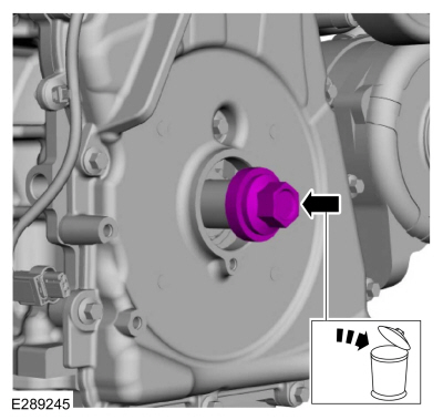
NOTICE:
Use care not to damage the engine front cover or the crankshaft when removing the seal.
Using the special tool, remove and discard the crankshaft front seal.
Use Special Service Tool: 303-409
(T92C-6700-CH)
Remover, Crankshaft Seal.
-
NOTE:
If necessary, retain the original crankshaft pulley bolt to use in other procedures.
Remove and discard the crankshaft pulley bolt.
-
Remove the bolts and the coolant pump pulley.
-
Detach wiring harness retainers from the engine front cover and stud bolts.
-
Remove the fasteners and the engine front cover.
-
NOTICE:
Only use a 3M™ Roloc® Bristle Disk (2-in white, part
number 07528) in a suitable tool turning at the recommended speed of
15,000 rpm, to clean the engine front cover. Do not use metal scrapers,
wire brushes or any other power abrasive disk to clean. These tools
cause scratches and gouges that make leak paths.
-
Make sure that the mating faces of the engine front cover are clean and free of foreign material.
Refer to: RTV Sealing Surface Cleaning and Preparation (303-00 Engine System - General Information, General Procedures).
Material: Motorcraft® Silicone Gasket Remover
/ ZC-30-A
Material: Motorcraft® Metal Brake Parts Cleaner
/ PM-4-A, PM-4-B
Material: Motorcraft® Metal Surface Prep Wipes
/ ZC-31-B
-
Thoroughly wash the engine front cover to remove any
foreign material, including any abrasive particles created during the
cleaning process.
 |
|
-
NOTICE:
Place clean, lint-free shop towels over exposed
engine cavities. Carefully remove the towels so foreign material is not
dropped into the engine. Any foreign material (including any material
created while cleaning gasket surfaces) that enters the oil passages or
the oil pan, may cause engine failure.
NOTICE:
Do not use metal scrapers, wire brushes, power
abrasive discs or 3M™ Roloc® Bristle Disk (2-in white part number 07528)
to clean the sealing surfaces. These tools cause scratches and gouges
that make leak paths. They also cause contamination that will cause
premature engine failure. Remove all traces of the gasket.
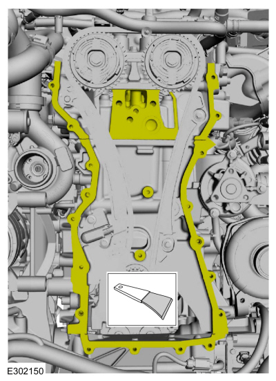
Make sure that the mating faces of the engine block and oil pan are clean and free of foreign material.
Refer to: RTV Sealing Surface Cleaning and Preparation (303-00 Engine System - General Information, General Procedures).
Use the General Equipment: Plastic Scraper
Material: Motorcraft® Silicone Gasket Remover
/ ZC-30-A
Material: Motorcraft® Metal Brake Parts Cleaner
/ PM-4-A, PM-4-B
Material: Motorcraft® Metal Surface Prep Wipes
/ ZC-31-B
 |
|
Installation
-
NOTE:
The engine front cover must be secured within 10
minutes of Silicone Gasket and Sealant application. If the engine front
cover is not secured within 10 minutes, the sealant must be removed and
the sealing area cleaned.
-
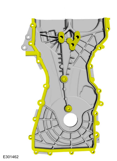
Apply a 3 mm (0.12 in) bead of silicone sealant on the 3 upper bosses, as shown.
Material: Motorcraft® High Performance Engine RTV Silicone
/ TA-357
(WSE-M4G323-A6)
-
Apply a 4 mm (0.16 in) bead of silicone sealant on the chamfer on the 2 lower bosses, as shown.
Material: Motorcraft® High Performance Engine RTV Silicone
/ TA-357
(WSE-M4G323-A6)
-
Apply a 5 mm (0.19 in) bead of silicone sealant on the chamfer, as shown.
Material: Motorcraft® High Performance Engine RTV Silicone
/ TA-357
(WSE-M4G323-A6)
.jpg) |
|
-
NOTE:
The engine front cover must be secured within 10
minutes of Silicone Gasket and Sealant application. If the engine front
cover is not secured within 10 minutes, the sealant must be removed and
the sealing area cleaned.
Apply a 15 mm (0.59 in) drop of silicone sealant at the
cylinder head-to-cylinder block and cylinder block-to-oil pan joint
areas.
Material: Motorcraft® High Performance Engine RTV Silicone
/ TA-357
(WSE-M4G323-A6)
-
Install the engine front cover and the fasteners and tighten in the sequence shown.
Torque:
Bolts 1 - 3:
35 lb.ft (48 Nm)
Bolts 4 - 22:
97 lb.in (11 Nm)
-
Attach wiring harness retainers to the engine front cover and stud bolts.
-
Install the coolant pump pulley and bolts finger-tight.
-
-
Lubricate the crankshaft front seal with clean engine oil.
-
Lubricate the crankshaft pulley with clean engine oil.
-
Position the crankshaft pulley onto the crankshaft with the access hole at the 6 o'clock position.
-
NOTE:
This step will correctly align the crankshaft pulley to the crankshaft.
Install an M6 bolt.
-
NOTICE:
The crankshaft must remain in the TDC
position during installation of the pulley bolt or damage to the engine
can occur. Therefore, the crankshaft pulley must be held in place with
the Crank Damper Holding Tool and the bolt should be installed using
hand tools only.
With the aid of an assistant and using the special tool, install the new crankshaft bolt and washer and tighten.
Use Special Service Tool: 303-1689
Holding Tool, Crank Damper.
Torque:
Stage 1:
74 lb.ft (100 Nm)
Stage 2:
90°
-
Remove the M6 bolt.
-
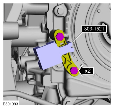
NOTE:
Do not tighten the CKP sensor bolts at this time.
Install the CKP sensor and the bolts finger tight.
-
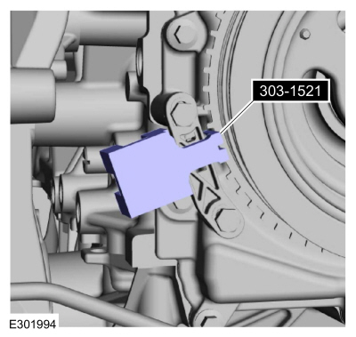
Install the special tool onto the CKP sensor and the tooth of the crankshaft pulley trigger wheel and tighten the bolts.
Use Special Service Tool: 303-1521
Alignment Tool, Crankshaft Position Sensor.
Torque:
97 lb.in (11 Nm)
-
Remove Special Service Tool: 303-1521
Alignment Tool, Crankshaft Position Sensor.
-
Connect the CKP sensor electrical connector.
-
Remove Special Service Tool: 303-507
Timing Peg, Crankshaft TDC.
-
Install the engine plug bolt.
Torque:
177 lb.in (20 Nm)
-
Remove Special Service Tool: 303-1685
Alignment Tool, Camshaft.
-
-
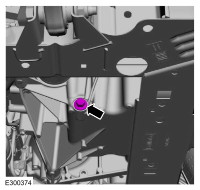
Remove the oil pan drain plug and drain the engine oil.
Use the General Equipment: Oil Drain Equipment
-
Install the oil drain plug.
Torque:
20 lb.ft (27 Nm)
-
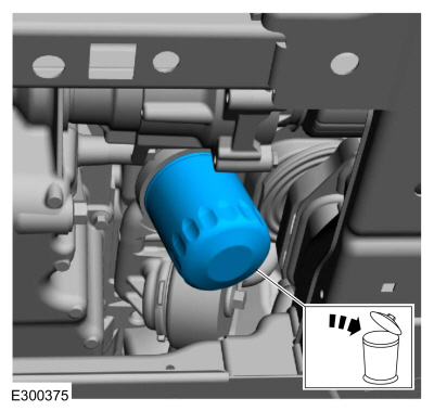
Remove and discard the engine oil filter.
Use the General Equipment: Oil Drain Equipment
-
Lubricate the new engine oil filter sealing surface with clean engine oil and install.
Torque:
Stage 1:
71 lb.in (8 Nm)
Stage 2:
180°
-
Install the rear underbody shield, bolts and the pin-type retainers.
Torque:
22 lb.in (2.5 Nm)
-
-
Install the underbody shield and the bolts.
Torque:
22 lb.in (2.5 Nm)
-
Install pin-type retainer.
-
Install the following items:
-
Install the high-pressure fuel pump drive unit.
Refer to: High-Pressure Fuel Pump Drive Unit (303-04A Fuel Charging and Controls - 2.3L EcoBoost (201kW/273PS), Removal and Installation).
-
Install the accessory drive belt tensioner.
Refer to: Accessory Drive Belt Tensioner (303-05A Accessory Drive - 2.3L EcoBoost (201kW/273PS), Removal and Installation).
-
Install the accessory drive belt.
Refer to: Accessory Drive Belt (303-05A Accessory Drive - 2.3L EcoBoost (201kW/273PS), Removal and Installation).
-
Tighten the coolant pump pulley bolts.
Torque:
18 lb.ft (25 Nm)
-
-
Install the air cleaner bracket and the bolts.
Torque:
59 lb.ft (80 Nm)
-
Attach the wiring harness retainer.
-
Attach the coolant hose retainer.
-
Install the air cleaner inlet tube.
-
Install the EVAP canister tube and connect the quick release coupling and the retainer.
Refer to: Quick Release Coupling (310-00A Fuel System - General Information - 2.3L EcoBoost (201kW/273PS), General Procedures).
-
Install the following items:
-
Install the EVAP canister purge valve.
Refer to: Evaporative Emission Canister Purge Valve (303-13A Evaporative Emissions - 2.3L EcoBoost (201kW/273PS), Removal and Installation).
-
Install the air cleaner outlet.
Refer to: Air Cleaner Outlet Pipe (303-12A Intake Air Distribution and Filtering - 2.3L EcoBoost (201kW/273PS), Removal and Installation).
-
Install the air cleaner.
Refer to: Air Cleaner (303-12A Intake Air Distribution and Filtering - 2.3L EcoBoost (201kW/273PS), Removal and Installation).
-
Connect the battery ground cable.
Refer to: Battery Disconnect and Connect (414-01 Battery, Mounting and Cables, General Procedures).
-
-
NOTE:
Lubricating the grommets with silicone grease
will aid in the installation of the engine appearance cover, and any
future removal and installation of the cover.
Lubricate each grommet with silicone grease.
Material: Motorcraft® Silicone Brake Caliper Grease and Dielectric Compound
/ XG-3-A
(ESE-M1C171-A)
-
Position the engine appearance cover onto engine with the grommet aligned with the stud.
-
Press down on the engine appearance cover at the
grommet location to attach the grommet onto the stud and install the
nuts.
Torque:
44 lb.in (5 Nm)
-
Install the suspension support bar and the bolts.
Torque:
22 lb.ft (30 Nm)
-
Fill the engine with clean engine oil.
Refer to: Specifications (303-01A Engine - 2.3L EcoBoost (201kW/273PS), Specifications).
-
Pressurize the fuel system.
Refer to: Fuel System Pressure Release (310-00A Fuel System - General Information - 2.3L EcoBoost (201kW/273PS), General Procedures).
-
Use the Powertrain Control Module (PCM) Misfire Monitor Profile Correction routine in the diagnostic scan tool.
Special Tool(s) /
General Equipment
Oil Drain Equipment
Hose Clamp Remover/Installer
Materials
Name
Specification
Motorcraft® High Performance Engine RTV SiliconeTA-357
WSE-M4..
Special Tool(s) /
General Equipment
303-050
(T70P-6000)
Lifting Bracket, Engine
303-F072Support Bar, Engine
Oil Drain Equipment
Cable Ties
Materials
Name
Specificatio..
Other information:
Special Tool(s) /
General Equipment
Transmission Jack
Wooden Block
Removal
With the vehicle in NEUTRAL, position it on a hoist.
Refer to: Jacking and Lifting - Overview (100-02 Jacking and Lifting, Description and Operation)...
Removal
WARNING:
The following procedure prescribes critical repair steps
required for correct restraint system operation during a crash. Follow
all notes and steps carefully. Failure to follow step instructions may
result in incorrect operation of the restraint system and increases the
risk of serious personal injury or death in a crash...
Categories
WARNING: Airbags can kill or injure a child in a child restraint. Never
place a rear-facing child restraint in front of an active airbag. If you must use
a forward-facing child restraint in the front seat, move the seat upon which the
child restraint is installed all the way back.
read more
.jpg)
.jpg)
.jpg)
.jpg)
.jpg)
.jpg)
.jpg)
.jpg)
.jpg)
.jpg)
.jpg)
.jpg)
.jpg)
.jpg)
.jpg)
.jpg)
.jpg)
.jpg)
.jpg)
.jpg)
.jpg)
.jpg)
.jpg)
.jpg)
.jpg)
.jpg)
 Removal and Installation - Cylinder Head
 Removal and Installation - Engine Mount LH