Ford Explorer: Suspension System - General Information / General Procedures - Ride Height Measurement
Special Tool(s) / General Equipment
| Surface Gauge |
Check
NOTE: Make sure that the vehicle is positioned on a flat, level surface and the tires are inflated to the correct pressure. Vehicle should have a full tank of fuel.
-
Before measuring ride height check:
-
Tires are inflated to the correct pressure.
-
Vehicle should have a full tank of fuel.
-
All fluids at proper levels.
-
No cargo inside the cab or bed.
-
Inspect for aftermarket equipment. Check for
aftermarket changes to the steering, suspension, wheel and tire
components (such as competition, heavy duty, etc.).
-
Tires are inflated to the correct pressure.
Ride Height Measurement — Front
-
NOTE: Make sure that the vehicle is positioned on a flat, level surface and the tires are inflated to the correct pressure. Vehicle should have a full tank of fuel.
-
Ride height = 3-2
-
Measure the distance between the flat level
surface and the center of the rear control arm ball joint cap
(measurement 2)
-
Measure the distance between the flat level
surface and the center of the rear control arm inboard bolt (measurement
3)
Use the General Equipment: Surface Gauge
-
Ride height = 3-2
.jpg) |
-
With the surface gauge positioned on a flat, level
surface, record the measurement of the surface gauge position
(measurement 2) and (measurement 3).
Use the General Equipment: Surface Gauge
.jpg) |
-
Subtract measurement 2 from measurement 3 to obtain the front ride height.
Ride Height Measurement — Rear
-
-
Ride height = 2-3
-
Measurement 2
-
Measurement 3
Use the General Equipment: Surface Gauge
-
Ride height = 2-3
.jpg) |
-
Measure the distance between the flat level surface
and the center of the toe link inboard cam bolt (measurement 2).
-
Measure the distance between the flat level surface
and the center of the toe link outboard bolt (measurement 3).
-
Subtract measurement 3 from measurement 2 to obtain the rear ride height.
 General Procedures - Rear Toe Adjustment
Special Tool(s) /
General Equipment
Wheel Alignment System
Adjustment
NOTICE:
Do not use any tools or equipment to move the wheel and tire
assembly or suspension components while che..
Other information:
Ford Explorer 2020-2026 Owners Manual: Switching Automatic High Beam Control On and Off
WARNING: Do not use the system in poor visibility, for example fog, heavy rain, spray or snow. Use the touchscreen to select the following: Select Settings. See Settings. Select Vehicle. Select Lighting. Activating the Automatic High Beam Control Switch the lighting control to the autolamps position...
Ford Explorer 2020-2026 Owners Manual: Audio Control
You can operate the following functions with the control: Press to decrease volume level. Press to increase volume level. Press to silence the current media Press to access phone mode or to answer a phone call. Press to end a phone call...
Categories
- Manuals Home
- 6th Generation Explorer Owners Manual
- 6th Generation Explorer Service Manual
- Engine - 2.3L EcoBoost (201kW/273PS)
- Body and Paint
- General Procedures - Brake Service Mode Activation and Deactivation
- New on site
- Most important about car
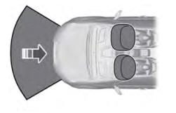
Driver and Passenger Airbags
WARNING: Do not place your arms on the airbag cover or through the steering wheel. Failure to follow this instruction could result in personal injury.
WARNING: Keep the areas in front of the airbags free from obstruction. Do not affix anything to or over the airbag covers. Objects could become projectiles during airbag deployment or in a sudden stop. Failure to follow this instruction could result in personal injury or death.
WARNING: Airbags can kill or injure a child in a child restraint. Never place a rear-facing child restraint in front of an active airbag. If you must use a forward-facing child restraint in the front seat, move the seat upon which the child restraint is installed all the way back.


