Ford Explorer: Rear Suspension / Removal and Installation - Wheel Knuckle
Ford Explorer 2020-2026 Service Manual / Chassis / Suspension / Rear Suspension / Removal and Installation - Wheel Knuckle
Removal
NOTICE: Suspension fasteners are critical parts that affect the performance of vital components and systems. Failure of these fasteners may result in major service expense. Use the same or equivalent parts if replacement is necessary. Do not use a replacement part of lesser quality or substitute design. Tighten fasteners as specified.
-
Remove the lower arm vertical link.
Refer to: Lower Arm Vertical Link (204-02 Rear Suspension, Removal and Installation).
-
Remove and discard the rear shock absorber lower nut.
.jpg) |
-
Remove the wheel bearing and wheel hub.
Refer to: Wheel Bearing and Wheel Hub (204-02 Rear Suspension, Removal and Installation).
-
Remove the bolts and the brake disc shield..
.jpg) |
-
-
Remove the wheel speed sensor bolt and position the wheel speed sensor aside.
-
Remove the brake hose bracket bolt and position the brake hose bracket aside.
-
Remove the wheel speed sensor bolt and position the wheel speed sensor aside.
.jpg) |
-
Support the halfshaft.
-
Remove and discard the toe link-to-wheel knuckle bolt and nut.
-
Remove and discard the upper arm-to-wheel knuckle bolt and nut.
-
Support the halfshaft and remove the wheel knuckle.
-
Remove and discard the toe link-to-wheel knuckle bolt and nut.
.jpg) |
Installation
-
NOTICE: Tighten the suspension bushing fasteners with the suspension loaded or with the weight of the vehicle resting on the wheels and tires, otherwise incorrect clamp load and bushing damage may occur.
-
Position the wheel knuckle and install the new upper arm-to-wheel knuckle bolt and nut.
Torque: 76 lb.ft (103 Nm)
-
Install the new toe link-to-wheel knuckle bolt and nut.
Torque: 129 lb.ft (175 Nm)
-
Position the wheel knuckle and install the new upper arm-to-wheel knuckle bolt and nut.
.jpg) |
-
-
Position the brake hose bracket and install the brake hose bracket bolt.
Torque: 133 lb.in (15 Nm)
-
Position the wheel speed sensor and install the wheel speed sensor bolt and wiring harness clip.
Torque: 133 lb.in (15 Nm)
-
Position the brake hose bracket and install the brake hose bracket bolt.
.jpg) |
-
Install the brake disc shield.
Torque: 133 lb.in (15 Nm)
.jpg) |
-
Install the wheel bearing and wheel hub.
Refer to: Wheel Bearing and Wheel Hub (204-02 Rear Suspension, Removal and Installation).
-
Install the new rear shock absorber lower nut.
Torque: 59 lb.ft (80 Nm)
.jpg) |
-
Install the lower arm vertical link.
Refer to: Lower Arm Vertical Link (204-02 Rear Suspension, Removal and Installation).
-
Check and if necessary adjust rear toe.
Refer to: Rear Toe Adjustment (204-00 Suspension System - General Information, General Procedures).
 Removal and Installation - Wheel Bearing and Wheel Hub
Special Tool(s) /
General Equipment
205-D070
(D93P-1175-B)
Remover, Front Wheel Hub
Removal
NOTICE:
Suspension fasteners are critical parts that affect the
performance of vital c..
 Removal and Installation - Wheel Studs
Special Tool(s) /
General Equipment
Hydraulic Press
Removal
Remove the wheel bearing and wheel hub.
Refer to: Wheel Bearing and Wheel Hub (204-02 Rear Suspension, Removal and Inst..
Other information:
Ford Explorer 2020-2026 Owners Manual: Economical Driving
Fuel economy is affected by several things such as how you drive, the conditions you drive under and how you maintain your vehicle. You may improve your fuel economy by keeping these things in mind: Accelerate and slow down in a smooth, moderate fashion...
Ford Explorer 2020-2026 Owners Manual: Under Hood Overview - 3.0L
A - Battery. See Changing the 12V Battery. B - Engine oil filler cap. See Engine Oil Check. C - Engine oil dipstick. See Engine Oil Dipstick. D - Brake fluid reservoir. See Brake Fluid Check. E - Engine compartment fuse box. See Fuses. F - Engine coolant reservoir...
Categories
- Manuals Home
- 6th Generation Explorer Owners Manual
- 6th Generation Explorer Service Manual
- Electric Parking Brake
- Engine - 2.3L EcoBoost (201kW/273PS)
- General Procedures - Brake Service Mode Activation and Deactivation
- New on site
- Most important about car
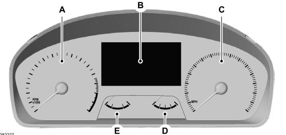
Gauges
4 Inch Display

A - Tachometer.
B - Information display.
C - Speedometer.
D - Fuel gauge.
E - Engine coolant temperature gauge.
Copyright © 2026 www.foexplorer.com
