Ford Explorer: Engine - 2.3L EcoBoost (201kW/273PS) / Removal and Installation - Oil Pan
Special Tool(s) /
General Equipment
.jpg) |
205-153
(T80T-4000-W)
Handle |
 |
303-096
(T74P-6150-A)
Installer, Camshaft Front Oil Seal
TKIT-2009TC-F |
 |
303-103
(T74P-6375-A)
Holding Tool, Flywheel
T74P-77000-A
TKIT-2009TC-F |
.jpg) |
303-1252
Stretchy Belt Remover/ Installer Tool
TKIT-2006UF-FLM
TKIT-2006UF-ROW |
.jpg) |
303-1521
Alignment Tool, Crankshaft Position Sensor
TKIT-2010C-FLM |
 |
303-1685
Alignment Tool, Camshaft |
.jpg) |
303-1687
Installer, VCT Solenoid Seal |
.jpg) |
303-1689
Holding Tool, Crank Damper |
.jpg) |
303-409
(T92C-6700-CH)
Remover, Crankshaft Seal
TKIT-1992-FH/FMH/FLMH
TKIT-1993-LMH/MH |
.jpg) |
303-507
Timing Peg, Crankshaft TDC
TKIT-2001N-FLM
TKIT-2001N-ROW |
| Mounting Stand |
Materials
| Name |
Specification |
Motorcraft® High Performance Engine RTV Silicone
TA-357 |
WSE-M4G323-A6
|
Removal
LHD AWD/LHD RWD
NOTICE:
Do not loosen or remove the crankshaft pulley bolt
without first installing the special tools as instructed in this
procedure. The crankshaft pulley and the crankshaft timing sprocket are
not keyed to the crankshaft. The crankshaft, the crankshaft sprocket and
the pulley are fitted together by friction. For that reason, the
crankshaft sprocket is also unfastened if the pulley bolt is loosened.
Before any repair requiring loosening or removal of the crankshaft
pulley bolt, the crankshaft and camshafts must be locked in place by the
special service tools, otherwise severe engine damage can occur.
NOTICE:
During engine repair procedures, cleanliness is
extremely important. All parts must be thoroughly cleaned and any
foreign material, including any material created while cleaning gasket
surfaces, that enters the oil passages, coolant passages or the oil pan,
can cause engine failure.
-
Remove the engine.
Refer to: Engine (303-01 Engine)
.
-
-
Remove the bolts and the flexplate.
-
Install engine on the mounting stand.
Use the General Equipment: Mounting Stand
-
Remove the engine lift equipment.
-
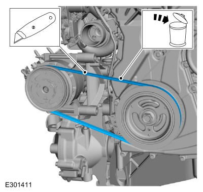
Cut and discard the A/C belt.
-
Loosen the coolant pump pulley bolts.
-
-
Install the tool and release the tension on the accessory drive belt tensioner.
-
Remove the accessory drive belt.
-
Release the tension and remove the tool.
-
-
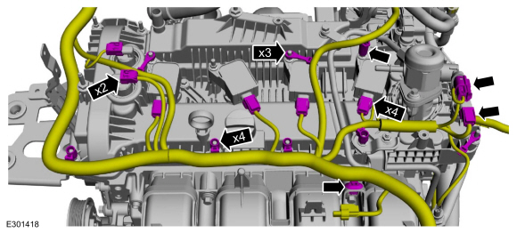
Disconnect the wiring harness electrical connectors.
-
Detach the wiring harness retainers.
-
-
Disconnect the wiring harness electrical connectors.
-
Detach the wiring harness retainers.
-
Remove the oil level indicator.
-
-
Disconnect the wiring harness electrical connectors.
-
Detach the wiring harness retainers.
-
-
Remove the coolant tube support bracket bolt.
-
Remove the bolt and the coolant tube support bracket.
-
-
Remove the EGR valve bracket nut.
-
Remove the bolt and the EGR valve bracket.
-
Remove the bolts and the coolant tube.
-
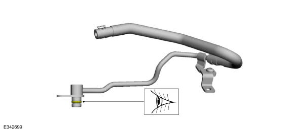
Inspect the coolant tube O-ring seal and replace if damaged.
-
Remove the bolts and the air cleaner bracket.
-
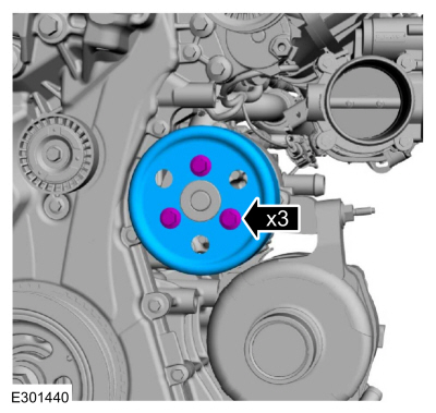
Remove the bolts and the coolant pump pulley.
-
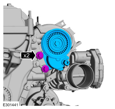
Remove the bolts and the accessory drive belt tensioner.
-
-
Remove the nut, bolts and the RH engine mount.
-
Discard the nut and bolts.
LHD AWD
-
Remove the bolts and the LH axle connector.
-
Remove and discard the axle connector seal.
-
Remove the bolts and the front axle assembly.
-
Remove and discard the front axle assembly seal.
LHD AWD/LHD RWD
-
Remove and discard the engine mount stud.
-
NOTE:
To release the fuel pressure in the high
pressure fuel tube, wrap the fuel injection pump flare nut with a shop
towel to absorb any residual fuel pressure during the loosening of the
fuel injection pump flare nut.
-
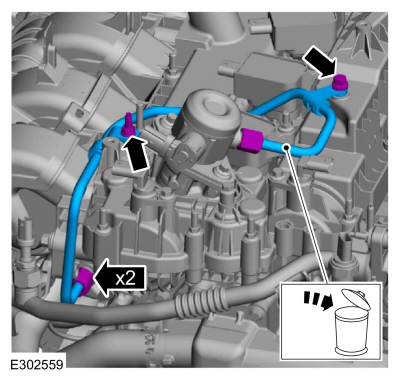
Remove the high-pressure fuel tube bolts.
-
Loosen the flare nuts, remove and discard the high-pressure fuel tube.
-
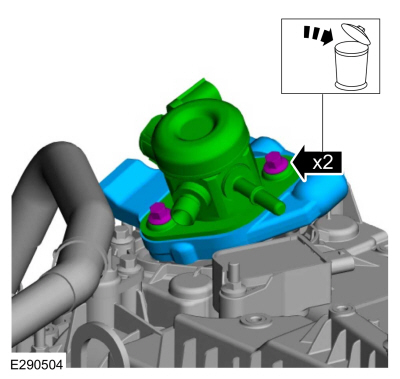
-
Remove and discard the bolts.
-
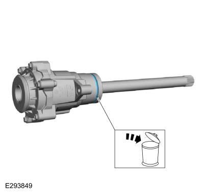
Remove the high-pressure fuel pump and the mounting plate.
-
Remove and discard the high-pressure fuel pump O-ring seal.
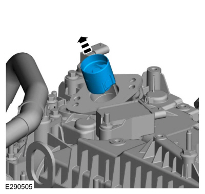
-
Remove the high-pressure fuel pump tappet.
-
NOTE:
Use compressed air to remove any foreign
material from the ignition coil-on-plugs and surrounding area before
removing the ignition coil-on-plugs.
NOTE:
When removing the ignition coil-on-plugs, a slight twisting motion will break the seal and ease removal.
Remove the stud bolts and the ignition coil-on-plugs.
-
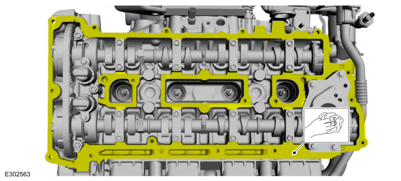
Loosen the fasteners and remove the valve cover.
-
Remove and discard the valve cover gaskets.
-
NOTE:
The VCT solenoid seals should only be replaced if they are damaged.
-
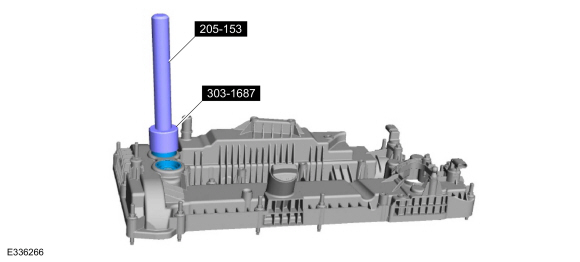
Inspect the VCT oil control solenoid seals for damage.
-
If damaged, using the special tools, remove and discard the VCT oil control solenoid seals.
Use Special Service Tool: 205-153
(T80T-4000-W)
Handle.
, 303-1687
Installer, VCT Solenoid Seal.
-
NOTICE:
Do not use metal scrapers, wire brushes, power
abrasive discs or other abrasive means to clean the sealing surfaces.
These tools cause scratches and gouges which make leak paths.
Make sure that the mating faces are clean and free of foreign material.
-
NOTICE:
Do not use metal scrapers, wire brushes, power
abrasive discs or other abrasive means to clean the sealing surfaces.
These tools cause scratches and gouges which make leak paths.
Make sure that the mating faces are clean and free of foreign material.
-
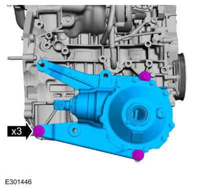
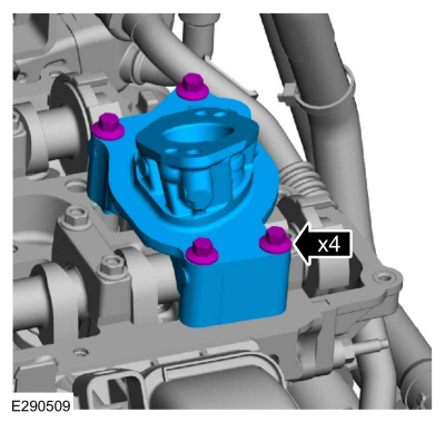
Remove the bolts and the high-pressure fuel pump drive unit.
-
Remove the bolts and the CKP sensor.
-
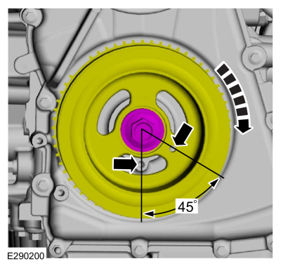
Turn the crankshaft clockwise until the No.1 piston is 45 degrees BTDC using the guide holes on the engine front cover and the crankshaft pulley.
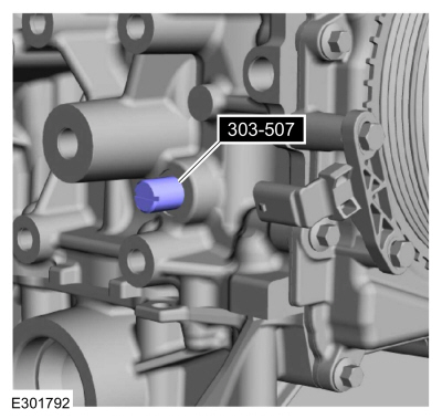
-
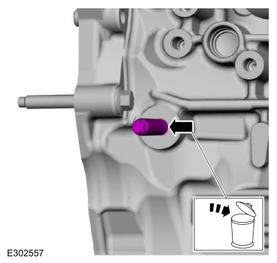
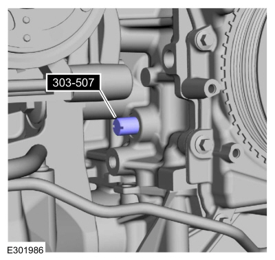
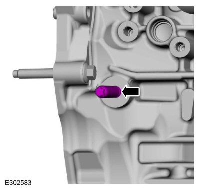
Remove the engine plug bolt.
-
Install Special Service Tool: 303-507
Timing Peg, Crankshaft TDC.
-
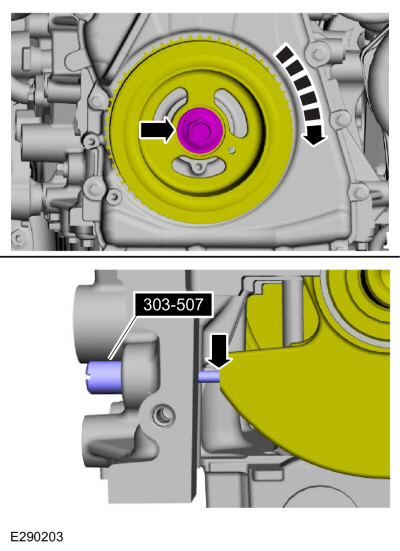
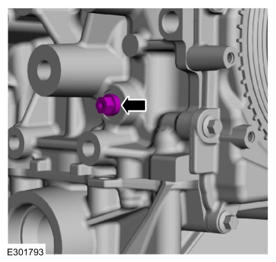
NOTE:
The Crankshaft TDC Timing Peg will contact the crankshaft and prevent it from turning past TDC. However, the crankshaft can still be rotated in the counterclockwise direction. The crankshaft must remain at the TDC position during the crankshaft pulley removal and installation.
NOTE:
The engine front cover is removed from graphic for clarity.
Rotate the crankshaft clockwise until the contacts the special tool.
Use Special Service Tool: 303-507
Timing Peg, Crankshaft TDC.
-
NOTICE:
The Camshaft Alignment Tool is for camshaft
alignment only. Using this tool to prevent engine rotation can result in
engine damage.
NOTE:
The camshaft timing slots are offset. If the Camshaft Alignment Tool cannot be installed, remove the TDC
Timing Peg and rotate the crankshaft three-fourths of a revolution
clockwise and repeat the previous 2 steps of this procedure.
Install Special Service Tool: 303-1685
Alignment Tool, Camshaft.
-
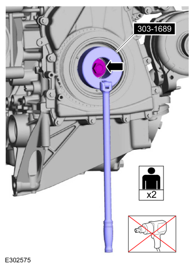
NOTICE:
The crankshaft must remain in the TDC
position during removal of the pulley bolt or damage to the engine can
occur. Therefore, the crankshaft pulley must be held in place with the
Crank Damper Holding Tool and the bolt should be removed using an air
impact wrench (1/2-in drive minimum).
-
Using the special tool, remove the bolt, washer and the crankshaft pulley.
Use Special Service Tool: 303-1689
Holding Tool, Crank Damper.
-
Install the old crankshaft pulley bolt.
-
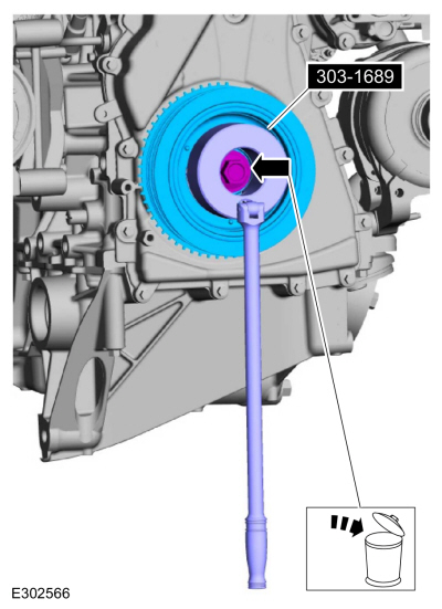
NOTICE:
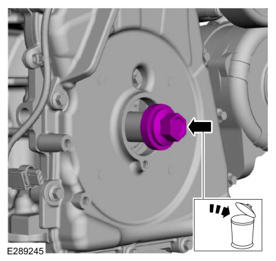
Use care not to damage the engine front cover or the crankshaft when removing the seal.
Using the special tool, remove and discard the crankshaft front seal.
Use Special Service Tool: 303-409
(T92C-6700-CH)
Remover, Crankshaft Seal.
-
NOTE:
If necessary, retain the original crankshaft pulley bolt to use in other procedures.
Remove and discard the crankshaft pulley bolt.
-
Remove the fasteners and the engine front cover.
-
Clean and prepare the RTV sealing surface.
Refer to: RTV Sealing Surface Cleaning and Preparation (303-00 Engine System - General Information, General Procedures).
-
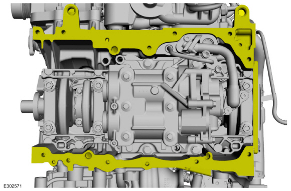
Clean and prepare the RTV sealing surface.
Refer to: RTV Sealing Surface Cleaning and Preparation (303-00 Engine System - General Information, General Procedures).
-
NOTICE:
Do not strike the oil pan sideways to remove,
the oil pan is doweled and will damage the oil pan and engine block.
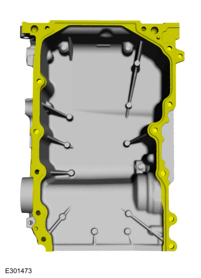
Remove the bolts and the oil pan.
-
Clean and prepare the RTV sealing surface.
Refer to: RTV Sealing Surface Cleaning and Preparation (303-00 Engine System - General Information, General Procedures).
-
Clean and prepare the RTV sealing surface.
Refer to: RTV Sealing Surface Cleaning and Preparation (303-00 Engine System - General Information, General Procedures).
Installation
LHD AWD/LHD RWD
-
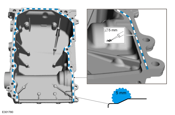
NOTE:
If the oil pan is not secured within 10 minutes
of silicone sealant application, the silicone sealant must be removed
and the sealing area cleaned. Allow to dry until there is no sign of
wetness, or 10 minutes, whichever is longer. Failure to follow this
procedure can cause future oil leakage.
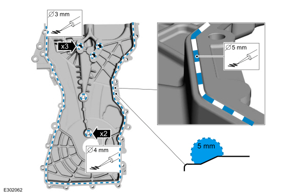
Apply a 5 mm bead of silicone sealant on the chamfer, as shown.
Material: Motorcraft® High Performance Engine RTV Silicone
/ TA-357
(WSE-M4G323-A6)
-
Install the oil pan and the bolts finger-tight.
-
Tighten the bolts in sequence shown.
Torque:
18 lb.ft (25 Nm)
-
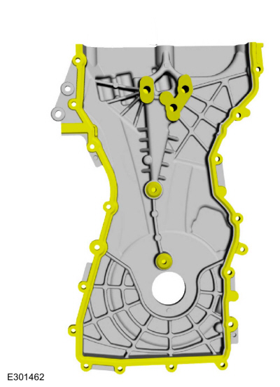
NOTE:
The engine front cover must be secured within 10
minutes of Silicone Gasket and Sealant application. If the engine front
cover is not secured within 10 minutes, the sealant must be removed and
the sealing area cleaned.
-
Apply a 3 mm (0.12 in) bead of silicone sealant on the 3 upper bosses, as shown.
Material: Motorcraft® High Performance Engine RTV Silicone
/ TA-357
(WSE-M4G323-A6)
-
Apply a 4 mm (0.16 in) bead of silicone sealant on the chamfer on the 2 lower bosses, as shown.
Material: Motorcraft® High Performance Engine RTV Silicone
/ TA-357
(WSE-M4G323-A6)
-
Apply a 5 mm (0.19 in) bead of silicone sealant on the chamfer, as shown.
Material: Motorcraft® High Performance Engine RTV Silicone
/ TA-357
(WSE-M4G323-A6)
 |
|
-
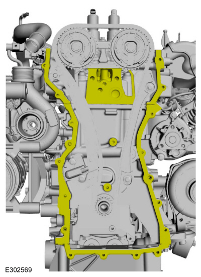
NOTE:
The engine front cover must be secured within 10
minutes of Silicone Gasket and Sealant application. If the engine front
cover is not secured within 10 minutes, the sealant must be removed and
the sealing area cleaned.
Apply a 15 mm (0.59 in) drop of silicone sealant at
the cylinder head-to-cylinder block and cylinder block-to-oil pan joint
areas.
Material: Motorcraft® High Performance Engine RTV Silicone
/ TA-357
(WSE-M4G323-A6)
-
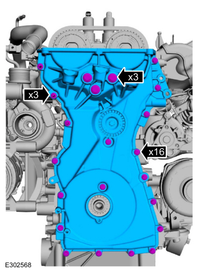
Install the engine front cover and the fasteners and tighten in the sequence shown.
Torque:
Bolts 1 - 3:
35 lb.ft (48 Nm)
Bolt 4:
18 lb.ft (25 Nm)
Bolts 5 - 22:
97 lb.in (11 Nm)
-
-
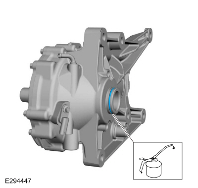
Lubricate the crankshaft front seal with clean engine oil.
-
Lubricate the crankshaft pulley with clean engine oil.
-
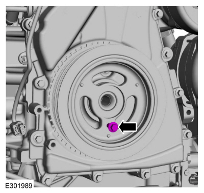
Position the crankshaft pulley onto the crankshaft with the access hole at the 6 o'clock position.
-
NOTE:
This step will correctly align the crankshaft pulley to the crankshaft.
Install an M6 bolt.
-
NOTICE:
The crankshaft must remain in the TDC
position during installation of the pulley bolt or damage to the engine
can occur. Therefore, the crankshaft pulley must be held in place with
the Crank Damper Holding Tool and the bolt should be installed using
hand tools only.
Using the special tool, install the new crankshaft bolt and washer and tighten.
Use Special Service Tool: 303-1689
Holding Tool, Crank Damper.
Torque:
Stage 1:
74 lb.ft (100 Nm)
Stage 2:
90°
-
Remove the M6 bolt.
-
NOTE:
Do not tighten the CKP sensor bolts at this time.
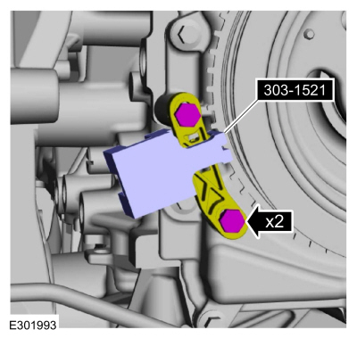
Install the CKP sensor and the bolts finger tight.
-
Install the special tool onto the CKP sensor and the tooth of the crankshaft pulley trigger wheel.
Use Special Service Tool: 303-1521
Alignment Tool, Crankshaft Position Sensor.
Torque:
97 lb.in (11 Nm)
-
Remove Special Service Tool: 303-1521
Alignment Tool, Crankshaft Position Sensor.
-
Remove Special Service Tool: 303-507
Timing Peg, Crankshaft TDC.
-
Install the engine plug bolt.
Torque:
177 lb.in (20 Nm)
-
Remove Special Service Tool: 303-1685
Alignment Tool, Camshaft.
-
Install the high-pressure fuel pump drive unit and the bolts.
Torque:
97 lb.in (11 Nm)
-
NOTE:
Installation of new seals is only required if damaged seals were removed during removal.
If removed, using the special tools, install the VCT oil control solenoid seals.
Use Special Service Tool: 205-153
(T80T-4000-W)
Handle.
, 303-1687
Installer, VCT Solenoid Seal.
-
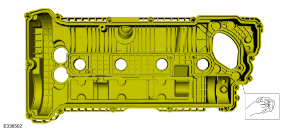
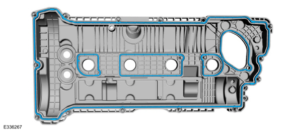
Install the new valve cover gaskets.
-
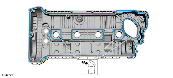
Apply a 5.5 mm (0.22 in) bead of silicone sealant in the 4 places shown.
Material: Motorcraft® High Performance Engine RTV Silicone
/ TA-357
(WSE-M4G323-A6)
-
NOTE:
The valve cover must be secured within 10
minutes of silicone gasket application. If the valve cover is not
secured within 10 minutes, the sealant must be removed and the sealing
area cleaned.
Install the valve cover and tighten the fasteners in sequence shown.
Torque:
97 lb.in (11 Nm)
-
Inspect and replace any ignition coil-on-plug rubber boots with cracks, rips or tears.
-
Install the ignition coil-on-plugs and the fasteners.
Torque:
97 lb.in (11 Nm)
-
NOTICE:
The high-pressure fuel pump tappet cam lobe must
be positioned at zero lift before installing the high-pressure fuel
pump drive unit.
Rotate the crankshaft to position the camshaft at zero lift.
-
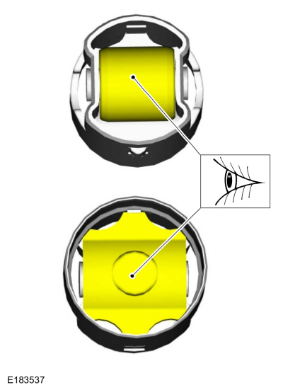
Inspect the high-pressure fuel pump tappet for flat
spots or scoring, especially in the indicated areas. If any damage is
found, inspect the high-pressure fuel pump and the high-pressure fuel
pump tappet drive lobe. Install new components as necessary.
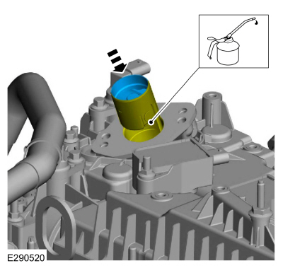
-
Lubricate the bore and the high-pressure fuel pump tappet with clean engine oil and install.
-
-
Inspect the mounting plate gasket, clean and replace the mounting plate gasket as needed.
-
Make sure that the mating faces are clean and free of foreign material.
-
Install a new high-pressure fuel pump O-ring seal.
-
NOTE:
Install new bolts.
Install the high-pressure fuel pump, mounting plate
and alternately tighten each new bolt one complete revolution until
seated in 2 stages.
Torque:
Stage 1:
115 lb.in (13 Nm)
Stage 2:
45°
-
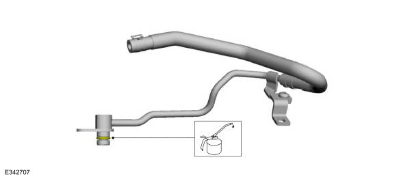
NOTE:
Install a new fuel tube.
-
Install the new fuel tube and the bolts finger-tight.
-
Install the flare nuts finger-tight.
-
Tighten the flare nuts in 2 stages.
Torque:
Stage 1:
89 lb.in (10 Nm)
Stage 2:
38°
-
Tighten the bolts.
Torque:
97 lb.in (11 Nm)
-
Install the new engine mount stud.
Torque:
35 lb.ft (48 Nm)
LHD AWD
-
Install a new front axle assembly seal and lubricate.
-
Install the front axle assembly and the bolts.
Torque:
Stage 1:
66 lb.ft (90 Nm)
Stage 2:
90°
-
Install a new axle connector seal and lubricate.
-
Install the LH axle connector and the bolts.
Torque:
26 lb.ft (35 Nm)
LHD AWD/LHD RWD
-
Clean the RH engine mount-to-engine block mating surfaces of any dirt or foreign material prior to installation.
-
Install the RH engine mount and tighten the new bolts and nuts in sequence shown.
Torque:
Stage 1:
66 lb.ft (90 Nm)
Stage 2:
90°
-
Install the accessory drive belt tensioner and the bolts.
Torque:
18 lb.ft (25 Nm)
-
Install the coolant pump pulley and the bolts finger tight.
-
Install the air cleaner bracket and the bolts.
Torque:
59 lb.ft (80 Nm)
-
Lubricate the coolant tube O-ring seal with clean engine coolant.
-
NOTE:
The coolant tube must be fully seated prior to tighten the bolt.
Install the coolant tube and the bolts.
Torque:
97 lb.in (11 Nm)
-
-
Install the EGR valve bracket and nut.
Torque:
97 lb.in (11 Nm)
-
Install the EGR valve bracket bolt.
Torque:
97 lb.in (11 Nm)
-
-
Install the coolant tube support bracket and the bolt.
Torque:
97 lb.in (11 Nm)
-
Install the coolant tube support bracket bolt.
Torque:
97 lb.in (11 Nm)
-
-
Attach the wiring harness retainers.
-
Connect the wiring harness electrical connectors.
-
Install the oil level indicator.
-
-
Attach the wiring harness retainers.
-
Connect the wiring harness electrical connectors.
-
-
Attach the wiring harness retainers.
-
Connect the wiring harness electrical connectors.
-
-
Install tool and release the tension on the accessory drive belt tensioner.
-
Install the accessory drive belt.
-
Release the tool and remove.
-
Tighten the coolant pump pulley bolts.
Torque:
18 lb.ft (25 Nm)
-
Position the A/C compressor belt onto the A/C
compressor pulley and around the Stretchy Belt Installer Tool on the
crankshaft pulley. Make sure that the belt is engaged with the
crankshaft pulley and rotate the crankshaft clockwise to install the A/C compressor belt.
Use Special Service Tool: 303-1252
Stretchy Belt Remover/ Installer Tool.
-
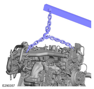
Install the engine lift equipment.
-
Remove engine from the mounting stand.
Use the General Equipment: Mounting Stand
-
-
Install Special Service Tool: 303-103
(T74P-6375-A)
Holding Tool, Flywheel.
-
Tighten the bolts in sequence shown in 3 stages.
Torque:
Stage 1:
37 lb.ft (50 Nm)
Stage 2:
59 lb.ft (80 Nm)
Stage 3:
83 lb.ft (112 Nm)
-
Install the engine.
Refer to: Engine (303-01 Engine)
.
Special Tool(s) /
General Equipment
Hose Clamp Remover/Installer
Locking Pliers
Removal
NOTE:
During engine repair procedures, cleanliness is extremely
important...
Special Tool(s) /
General Equipment
100-002
(TOOL-4201-C)
Holding Fixture with Dial Indicator Gauge
303-1685Alignment Tool, Camshaft
303-1688Preload Tool, Balance Shaft
3..
Other information:
Cleaning
WARNING:
Do not bleach or re-dye the seatbelt webbing, as the webbing
may weaken. Failure to follow this instruction may increase the risk of
serious personal injury or death in a crash.
Refer to the owner's literature for information on
seatbelt care and the recommended cleaning solution to use...
Diagnostic Trouble Code (DTC) Chart
Diagnostics in this manual assume a certain skill level and knowledge of Ford-specific diagnostic practices. REFER to: Diagnostic Methods (100-00 General Information, Description and Operation).
Diagnostic Trouble Code Chart
Module
DTC
Description
Action
DDM
B1C03:2..
Categories
When these locks are set, you cannot open the rear doors from the inside.

A child safety lock is on the rear edge of each rear door. You must set the child
safety lock separately on each door.
Left-Hand Side
read more
.jpg)
.jpg)
.jpg)
.jpg)
.jpg)
.jpg)
.jpg)
.jpg)
.jpg)
.jpg)
.jpg)
.jpg)
.jpg)
.jpg)
.jpg)

.jpg)
.jpg)
.jpg)
.jpg)
.jpg)
.jpg)
.jpg)
.jpg)
.jpg)
.jpg)
.jpg)
.jpg)
.jpg)
.jpg)
.jpg)
.jpg)
.jpg)

.jpg)
.jpg)
.jpg)
.jpg)
.jpg)
.jpg)
.jpg)
.jpg)
.jpg)
.jpg)
.jpg)
.jpg)
.jpg)
.jpg)
.jpg)
.jpg)
 Removal and Installation - Oil Cooler
 Removal and Installation - Oil Pump