Ford Explorer: Automatic Transmission - 10-Speed Automatic Transmission – 10R60 / Removal and Installation - Main Control Valve Body
Removal
NOTE: The Solenoid Body Strategy Data Download procedure must be performed if a new main control valve body is installed.
-
Remove the transmission fluid pan gasket and filter.
Refer to: Transmission Fluid Pan, Gasket and Filter (307-01A Automatic Transmission - 10-Speed Automatic Transmission – 10R60, Removal and Installation).
Refer to: Transmission Fluid Pan, Gasket and Filter (307-01A Automatic Transmission - 10-Speed Automatic Transmission – 10R60, Removal and Installation).
-
Place the vehicle in manual park overide.
Refer to: Transmission Park by Wire Manual Release (307-05A Automatic Transmission External Controls - 10-Speed Automatic Transmission – 10R60, General Procedures).
Auto-Start-Stop vehicles
-
Remove the bolt and the transmission fluid auxiliary pump tube.
.jpg) |
-
Remove the transmission fluid auxiliary pump tube seal.
.jpg) |
All vehicles
-
NOTE: The internal wiring harness electrical connector can not be fully disconnected until lowering the main control valve body.
Unlock the internal wiring harness electrical connector.
.jpg) |
-
Remove the main control valve body.
-
While supporting the main control valve body, remove the main control-to-transmission case bolts.
-
Disconnect the internal wiring harness electrical connector while removing the main control valve body.
-
While supporting the main control valve body, remove the main control-to-transmission case bolts.
.jpg) |
-
Remove the main control assembly to transmission fluid pump seal.
.jpg) |
Installation
-
Install the main control assembly to transmission fluid pump seal.
|
-
NOTICE: Do not install a 71 mm length bolt in the location shown or the transmission clutch and planetary container will be damaged and result in transmission failure.
Loosely install the main control valve body.
-
Connect the internal wiring harness electrical connector while installing the main control valve body.
-
Align the TR sensor with the park pawl lock valve.
-
Align the guide pins on the main control valve body with the alignment holes in the transmission case.
-
Loosely install the 68 mm length main control-to-transmission case bolts.
-
Connect the internal wiring harness electrical connector while installing the main control valve body.
.jpg) |
-
Lock the internal wiring harness electrical connector.
|
Auto-Start-Stop vehicles
-
Install the transmission fluid auxiliary pump tube seal.
|
-
Inspect the transmission fluid auxiliary pump tube O-ring.
.jpg) |
-
Install the transmission fluid auxiliary pump tube and loosely install the bolt.
|
All vehicles
-
-
Tighten the bolts No. 1-8 in the sequence shown.
Torque: 89 lb.in (10 Nm)
-
If equipped with Auto-Start-Stop, tighten bolt No. 9
Torque: 106 lb.in (12 Nm)
-
Tighten the bolts No. 1-8 in the sequence shown.
.jpg) |
-
Install the transmission fluid pan gasket and filter.
Refer to: Transmission Fluid Pan, Gasket and Filter (307-01A Automatic Transmission - 10-Speed Automatic Transmission – 10R60, Removal and Installation).
Refer to: Transmission Fluid Pan, Gasket and Filter (307-01A Automatic Transmission - 10-Speed Automatic Transmission – 10R60, Removal and Installation).
-
NOTICE: When the repair is complete, the park overide release must be returned to the NORMAL OPERATING POSITION or vehicle damage can occur.
Verify that the park override release is in the normal operating position.
Refer to: Transmission Park by Wire Manual Release (307-05A Automatic Transmission External Controls - 10-Speed Automatic Transmission – 10R60, General Procedures).
-
NOTE: The solenoid body strategy data file and solenoid body identification must be updated anytime a new main control valve body is installed. A new main control valve body service tag must be installed over the current main control valve body service tag on the transmission case.
If a new main control valve body was installed, download a new transmission strategy.
Refer to: Transmission Strategy Download (307-01A Automatic Transmission - 10-Speed Automatic Transmission – 10R60, General Procedures).
 Removal and Installation - Intermediate Speed Sensor B (ISSB)
Removal
Remove the main control valve body.
Refer to: Main Control Valve Body (307-01B Automatic Transmission - 10-Speed Automatic Transmission – 10R80, Removal and Installation)...
 Removal and Installation - Output Shaft Seal
Special Tool(s) /
General Equipment
100-001
(T50T-100-A)
Slide Hammer
205-1018Installation Tube
307-309Remover, Torque Converter SealTKIT-1994-FMH/FLMHTKIT-1994-LMH/MHTKIT-1994-..
Other information:
Ford Explorer 2020-2026 Service Manual: Specifications
General Specifications Item Specification Plug Weld hole 8 mm (0.315 in) Weld Wire ER70S-3 0.9 mm (0.0354 in) - 1.1 mm (0.0433 in) Weld Wire ER70S-6 0...
Ford Explorer 2020-2026 Service Manual: Disassembly and Assembly - Driveshaft Universal Joint
Special Tool(s) / General Equipment 205-086 (T74P-4635-C) Installer/Remover, C-Frame and Screw Materials Name Specification Motorcraft® Premium Long-Life GreaseXG-1-E1 ESA-M1C75-B DISASSEMBLY NOTICE: Do not, under any circumstance, clamp the driveshaft assembly in the jaws of a vise or similar holding fixture...
Categories
- Manuals Home
- 6th Generation Explorer Owners Manual
- 6th Generation Explorer Service Manual
- General Procedures - Transmission Fluid Drain and Refill
- Description and Operation - Jacking and Lifting - Overview
- Automatic Transmission - 10-Speed Automatic Transmission – 10R60
- New on site
- Most important about car
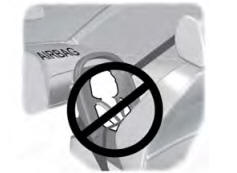
Children and Airbags
WARNING: Airbags can kill or injure a child in a child restraint. Never place a rear-facing child restraint in front of an active airbag. If you must use a forward-facing child restraint in the front seat, move the seat upon which the child restraint is installed all the way back.