Ford Explorer: Uni-Body, Subframe and Mounting System / Removal and Installation - Front Subframe - 2.3L EcoBoost™
Special Tool(s) /
General Equipment
.jpg) |
303-050
(T70P-6000)
Lifting Bracket, Engine |
.jpg) |
303-F072
Support Bar, Engine |
| Cable Ties |
Removal
NOTICE:
Suspension fasteners are critical parts that affect
performance of vital components and systems. Failure of these fasteners
may result in major service expense. Use the same or equivalent parts if
replacement is necessary. Do not use a replacement part of lesser
quality or substitute design. Tighten fasteners as specified.
-
Measure the distance from the center of the hub to the
lip of the fender with the vehicle in a level, static ground position
(curb height).
-
With the vehicle in NEUTRAL, position it on a hoist.
Refer to: Jacking and Lifting - Overview (100-02 Jacking and Lifting, Description and Operation).
-
Using a suitable holding device, hold the steering wheel in the straight-ahead position.
-
Remove the retainers and the upper radiator panel.
-
Remove the bolts and the suspension support bar.
Torque:
22 lb.ft (30 Nm)
-
NOTICE:
Do not pull the engine appearance cover forward or
sideways to remove. Failure to press straight upward on the underside of
the cover at the attachment points may result in damage to the cover or
engine components.
-
Remove the engine appearance cover nuts.
-
NOTE:
Lubricating the grommets with silicone grease
will aid in the installation of the engine appearance cover, and any
future removal and installation of the cover.
Place your hand under the engine appearance cover at
the grommet location and push straight up to release the grommet from
the stud.
-
After the grommet has been released from the stud, remove the appearance cover from the engine.
-
Drain the cooling system.
Refer to: Engine Cooling System Draining, Vacuum Filling and Bleeding (303-03A Engine Cooling - 2.3L EcoBoost (201kW/273PS), General Procedures).
-
Remove the cowl panel.
Refer to: Cowl Panel (501-02 Front End Body Panels, Removal and Installation).
-
-
.jpg) WARNING:
Do not reuse steering column shaft bolts. This
may result in fastener failure and steering column shaft detachment or
loss of steering control. Failure to follow this instruction may result
in serious injury to vehicle occupant(s).
WARNING:
Do not reuse steering column shaft bolts. This
may result in fastener failure and steering column shaft detachment or
loss of steering control. Failure to follow this instruction may result
in serious injury to vehicle occupant(s).
Remove and discard the steering column shaft bolt.
Torque:
22 lb.ft (30 Nm)
-
Separate the steering column shaft coupler from the EPAS gear.
-
Using cable ties or mechanics wire through the upper location holes, to support the cooling module.
Use the General Equipment: Cable Ties
-
Remove the bolt (Enhanced Hexalobular or TORX PLUS ®
Acument Intellectual Properties, LLC as the owner) and the shield.
Torque:
18 lb.ft (25 Nm)
-
Detach the retainers, remove the bolt and position the ground wire aside.
Torque:
159 lb.in (18 Nm)
-
Using the ground wire bolt, install the special tool.
Install Special Service Tool: 303-050
(T70P-6000)
Lifting Bracket, Engine.
-
NOTE:
Make sure to use the round feet on the shock towers or damage may occur.
Install Special Service Tool: 303-F072
Support Bar, Engine.
-
Remove the LH and RH front wheels and tires.
Refer to: Wheel and Tire (204-04A Wheels and Tires, Removal and Installation).
-
If equipped.
-
Remove pin-type retainer.
-
Remove the bolts and the underbody shield.
Torque:
22 lb.in (2.5 Nm)
-
If equipped.
-
Remove the pin-type retainers, bolts and the rear underbody shield.
Torque:
22 lb.in (2.5 Nm)
-
On both sides.
Remove the wheel arch liner to front subframe retainers.
-
NOTE:
The stabilizer bar links are designed with low friction ball joints that have a low breakaway torque.
NOTE:
Use the hex-holding feature to prevent the ball stud
from turning while removing or installing the stabilizer bar link nut.
-
On both sides.
Remove and discard the front stabilizer bar link lower nut.
Torque:
129 lb.ft (175 Nm)
-
Position aside the front stabilizer bar link.
-
NOTICE:
Do not use a hammer to separate the tie rod end from
the wheel knuckle or damage to the wheel knuckle may result.
NOTICE:
Use care when installing the tie rod separator or damage to the tie rod end boot may occur.
NOTE:
Use the hex-holding feature to prevent turning of the stud while removing the tie rod end nut.
-
On both sides.
Remove and discard the tie rod end nut.
Torque:
52 lb.ft (70 Nm)
-
On both sides.
Separate the tie rod end from the wheel knuckle.
-
On both sides.
Remove and discard the front lower arm outboard nut.
Torque:
66 lb.ft (90 Nm)
AWD
-
NOTICE:
Failure to remove the AWD front halfshaft during
lower control arm removal will cause damage to the front halfshaft.
NOTE:
Use non-splined bolts in the lower strut to knuckle assy.
Remove the front halfshaft.
Refer to: Halfshaft (205-04 Front Drive Halfshafts, Removal and Installation).
All vehicles
-
NOTICE:
Do not use a prying device or separator fork
between the ball joint and the wheel knuckle. Damage to the ball joint
or ball joint seal may result. Only use the pry bar by inserting it into
the lower arm body opening.
NOTICE:
Use care when releasing the lower arm and wheel
knuckle into the resting position or damage to the ball joint seal may
occur.
-
Separate the front lower arm from the wheel Knuckle.
-
NOTE:
If equipped with dynamic suspension.
-
Disconnect the ride height sensor electrical connector and separate the wiring harness guide.
-
Remove the ride height sensor arm anchor plate bolt.
-
-
Remove and discard the rear lower arm outboard nut.
Torque:
173 lb.ft (235 Nm)
-
Dettach the rear lower arm from the wheel knuckle.
-
Remove the retainers and the LH (left-hand) steering gear splash shield
-
Remove the retainers and the RH (right-hand) steering gear splash shield.
-
Disconnect the EPAS gear harness electrical connectors.
-
Detach the HO2S wiring harness retainers from the RH subframe.
-
Unclip and position aside the EPAS gear harness.
-
Detach the wiring harness retainers from the LH subframe.
-
Detach the wiring harness retainers from the RH subframe.
-
Detach the coolant tube retainers from the front of the subframe.
-
Remove the bolts and position the underbody shield aside.
-
Remove the front radiator support bar bolts.
Torque:
46 lb.ft (63 Nm)
-
Support the front and rear of the subframe with adjustable jack stands.
-
NOTE:
RH side shown, LH side similar
On both side
Remove and discard the engine mount bolts.
Torque:
76 lb.ft (103 Nm)
-
On both sides.
Mark the front subframe location.
-
On both sides.
Mark the rear subframe location.
-
Remove and discard the rear subframe bolts.
Torque:
Stage 1:
52 lb.ft (70 Nm)
Stage 2:
90°
-
Remove and discard the middle subframe bolts.
Torque:
195 lb.ft (265 Nm)
-
Remove and discard the front subframe bolts.
Torque:
195 lb.ft (265 Nm)
-
With the aid of an assistant, lower the front subframe assembly from the vehicle.
Installation
-
To install, reverse the removal procedure.
-
Install the wheels and tires.
Refer to: Wheel and Tire (204-04A Wheels and Tires, Removal and Installation).
-
NOTE:
Use non-splined bolts in the lower strut to knuckle assy.
Recheck alignment to verify camber change and adjust front toe if necessary.
Refer to: Front Toe Adjustment (204-00 Suspension System - General Information, General Procedures).
Overview
The front subframe is bolted to the body and is used to:
aid in structural support.
provide mounting surfaces for the steering gear...
Special Tool(s) /
General Equipment
300-OTC1585AEPowertrain Lift
Vehicle/Axle Stands
Wooden Block
Removal
NOTICE:
Suspension fasteners are critical parts that affect the
..
Other information:
Special Tool(s)
Vehicle Communication & Measurement Module (VCMM™) Base Kit 164-R9822 / 164-R9823
EngineEAR107-R2100Chassis EarsJSP97170 Squeak And Rattle Kit164-R4900
Ultrasonic Leak Detector134-R0135
Diagnostic Theory
The shortest route to an accurate diagnosis results from:
System knowledge, including comparison with a kn..
Removal
NOTE:
Removal steps in this procedure may contain installation details.
Remove the roof opening panel glass.
Refer to: Roof Opening Panel Glass (501-17 Roof Opening Panel, Removal and Installation).
Remove the roof opening panel fixed glass...
Categories
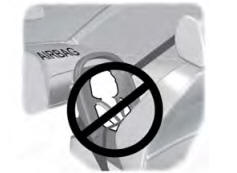
WARNING: Airbags can kill or injure a child in a child restraint. Never
place a rear-facing child restraint in front of an active airbag. If you must use
a forward-facing child restraint in the front seat, move the seat upon which the
child restraint is installed all the way back.
read more
.jpg)
.jpg)
.jpg)
.jpg)
.jpg)
.jpg)
.jpg)
.jpg)
.jpg)
.jpg)
.jpg)
.jpg)
.jpg)
.jpg)
.jpg)
.jpg)
.jpg)
.jpg)
.jpg)
.jpg)
.jpg)
.jpg)
.jpg)
.jpg)
.jpg)
.jpg)
.jpg)
.jpg)
.jpg)
.jpg)
.jpg)
.jpg)
.jpg)
.jpg)
.jpg)
.jpg)
.jpg)
.jpg)
 Description and Operation - Frame Assembly - Overview
 Removal and Installation - Rear Subframe