Ford Explorer: Fuel System - General Information - 2.3L EcoBoost (201kW/273PS) / General Procedures - Fuel System Pressure Release
Ford Explorer 2020-2026 Service Manual / Powertrain / Fuel System - General Information / Fuel System - General Information - 2.3L EcoBoost (201kW/273PS) / General Procedures - Fuel System Pressure Release
Pressure release
-
With the vehicle in NEUTRAL, position it on a hoist.
Refer to: Jacking and Lifting - Overview (100-02 Jacking and Lifting, Description and Operation).
-
-
Remove the nuts and bolts.
Torque: 55 lb.in (6.2 Nm)
-
Remove the retainers and air deflector.
-
Remove the nuts and bolts.
.jpg) |
-
Disconnect the Fuel Pump Control Module electrical connector.
.jpg) |
-
Start the engine and allow it to idle until it stalls.
-
After the engine stalls, crank the engine for
approximately 5 seconds to make sure the fuel rail pressure has been
released.
-
Turn the ignition switch to the OFF position.
-
Disconnect battery ground cable.
Refer to: Battery Disconnect and Connect (414-01 Battery, Mounting and Cables, General Procedures).
-
When the fuel system service is complete, reconnect the Fuel Pump Control Module electrical connector.
.jpg) |
-
-
Tighten the nuts and bolts.
Torque: 55 lb.in (6.2 Nm)
-
Install the retainers and the air deflector.
-
Tighten the nuts and bolts.
.jpg) |
-
Reconnect battery ground cable.
Refer to: Battery Disconnect and Connect (414-01 Battery, Mounting and Cables, General Procedures).
-
Cycle the ignition key and wait 3 seconds to pressurize
the fuel system. Check for leaks before starting the engine.
-
When service on the high pressure fuel system (high
pressure pump, fuel injectors and fuel rail) is completed, start the
engine and check for leaks.
 General Procedures - Fuel System Pressure Check
Special Tool(s) /
General Equipment
310-D009
(D95L-7211-A)
Fuel Pressure Test Kit
Check
NOTE:
This Fuel System Pressure Check is for the low pressure side of the system...
 General Procedures - Fuel Tank Draining
Special Tool(s) /
General Equipment
292-00004Fuel Tanker 100 GPM
Draining
WARNING:
Before beginning any service procedure in this
section, refer to Safety Warnings..
Other information:
Ford Explorer 2020-2026 Owners Manual: SPECIAL NOTICES
New Vehicle Limited Warranty Vehicles sold in the United States and Canada For a detailed description of what is covered by your New Vehicle Limited Warranty, see your warranty guide that is available online. For more information, refer to our website and download your copy of the warranty guide...
Ford Explorer 2020-2026 Service Manual: Description and Operation - E Clutch
Overview Item Description 1 SSE 2 E clutch control valve 3 Clutch gain control valve 4 E clutch apply circuit 5 E clutch piston 6 E clutch assembly 7 Shell and sun gear No...
Categories
- Manuals Home
- 6th Generation Explorer Owners Manual
- 6th Generation Explorer Service Manual
- Removal and Installation - Front Halfshaft Speed Sensor
- General Procedures - Brake Service Mode Activation and Deactivation
- Automatic Transmission - 10-Speed Automatic Transmission – 10R60
- New on site
- Most important about car
Child Safety Locks
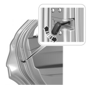
When these locks are set, you cannot open the rear doors from the inside.

A child safety lock is on the rear edge of each rear door. You must set the child safety lock separately on each door.
Left-Hand Side
Copyright © 2026 www.foexplorer.com
