Ford Explorer: Fuel System - General Information - 2.3L EcoBoost (201kW/273PS) / Diagnosis and Testing - Fuel System - 2.3L EcoBoost (201kW/273PS)
Symptom Chart(s)
Symptom Chart: Fuel System
NOTE: The fuel tank inlet check valve prevents spitback of fuel during and after refueling.
Diagnostics in this manual assume a certain skill level and knowledge of Ford-specific diagnostic practices.
REFER to: Diagnostic Methods (100-00 General Information, Description and Operation).
for information regarding Ford-specific diagnostic practices.
NOTE: The following procedure diagnoses a slow to fill concern only. For all other concerns, refer to Refer to Powertrain Control/Emissions Diagnosis (PC/ED) manual.
Symptom Chart
| Condition | Possible Sources | Actions |
|---|---|---|
| Slow to fill |
|
GO to Pinpoint Test A |
| All other fuel system concerns | Fuel system components | Refer to Powertrain Control/Emissions Diagnosis (PC/ED) manual. |
Diagnostic Routine(s)
|
Normal Operation and Fault Conditions Under normal operation, fuel should flow at a steady rate through the fuel tank filler pipe into the fuel tank. As fuel enters the fuel tank air is vented through the filler pipe or the ORVR system. Possible Sources
|
||||
| A1 CHECK THE FUEL SYSTEM COMPONENTS FOR SIGNS OF DAMAGE | ||||
Are any of the components damaged?
|
||||
| A2 CHECK THE SYSTEM FOR ANY EVAP (EVAPORATIVE EMISSION) DTC'S | ||||
Are any of these DTC's present?
|
||||
| A3 MONITOR THE FTP WHILE FILLING THE FUEL TANK | ||||
Is the FTP less than 1" H2O / 0.25 kPa?
|
||||
| A4 INSPECT THE FUEL FILL PIPE & VAPOR RECIRCULATION LINE ASSEMBLY | ||||
Is the fuel fill pipe assembly blocked or damaged?
|
||||
| A5 REFUEL USING A DIFFERENT FUEL FILL NOZZLE | ||||
Is the FTP less than 12" H2O / 3.0 kPa?
|
||||
| A6 DIAGNOSE THE FRESH AIR HOSE | ||||
Is the fresh air hose blocked or damaged?
|
||||
| A7 DIAGNOSE THE EVAP CANISTER | ||||
Is the FTP less than 12" H2O / 3.0 kPa?
|
P04B0
Refer to Wiring Diagrams Cell 023-9 for schematic and connector information.
Possible Causes
- Wiring, terminals and connectors
Visual Inspection and Diagnostic Pre-checks
- Fuel Vapor Vent Valve FVVV (also known as Refueling Valve)
NOTE: P04B0 is caused when the refuel valve control circuit is Open
This diagnostic runs when the cabin refuel button is pressed to open the refueling valve to allow the vehicle to be fueled without spit back.
PINPOINT TEST B : DTC P04B0
| NOTE: P04B0 is caused when the refuel valve control circuit is Open | ||||||||||
| B1 CHECK THE SYSTEM FOR ANY EVAP (EVAPORATIVE EMISSION) DTCS | ||||||||||
Is DTC P04B0 present?
|
||||||||||
| B2 CHECK THE FUEL VAPOR VENT VALVE FVVV (ALSO KNOWN AS THE REFUELING VALVE) CIRCUITS FOR AN OPEN : | ||||||||||
Is Resistance between 7.5 – 9.5 ohms?
|
||||||||||
| B3 CHECK FUEL VAPOR VENT VALVE CIRCUIT FVVV (ALSO KNOWN AS THE REFUELING VALVE) FOR A SHORT TO VOLTAGE : | ||||||||||
Is any voltage present?
|
||||||||||
| B4 CHECK FUEL VAPOR VENT VALVE (ALSO KNOWN AS THE REFUELING VALVE) CIRCUITS FOR A SHORT TO GROUND : | ||||||||||
Are the resistances greater than 10,000 ohms?
|
||||||||||
| B5 CHECK FUEL VAPOR VENT VALVE (ALSO KNOWN AS THE REFUELING VALVE) CIRCUITS FOR A OPEN : | ||||||||||
Is the resistance less than 3 ohms?
|
.jpg)
.jpg)
DTC P04B4
Refer to Wiring Diagrams Cell 023-9 for schematic and connector information.
Diagnostics
in this manual assume a certain skill level and knowledge of
Ford-specific diagnostic practices. For information about these
practices,
REFER to: Diagnostic Methods (100-00 General Information, Description and Operation).
Refueling Valve opens to depressurize the tank on Fuel door button press.
On the instant of button press when the pressure or vacuum in the tank is higher than a safe refuel range ( -6.98 In.H2O to +6.98 In.H2O), the refilling valve opens to depressurize the tank to enable a safe refuel (Tank Pressure at 0.25 PSI (6.93 In.H2O)).
This pinpoint test is intended to diagnose the following:
Possible Sources:
- Broken refueling valve
- Broken FTP (Fuel Tank Pressure) sensor
- Refueling Valve (RV) circuit
Check for any of the circuit codes (P04BA, P04C1, P04C2, P04C9, and P04CD) related to the door operation prior to following the test procedure below)
PINPOINT TEST C : P04B4
| C1 CHECK THE REFUELING VALVE STUCK CLOSED | ||||||||||||||||
Does the Tank Pressure drop to less than 0.25 PSI (6.92 In.H20)?
|
||||||||||||||||
| C2 CHECK THE FTP (FUEL TANK PRESSURE) SENSOR VOLTAGE WITH THE CAPLESS FUEL TANK FILLER PIPE OPENED | ||||||||||||||||
Is FTP (Fuel Tank Pressure) Voltage reading between 1.4V -1.54 V?
|
||||||||||||||||
| C3 CHECK THE FUEL VAPOR VENT VALVE CIRCUITS FOR A SHORT TO VOLTAGE | ||||||||||||||||
Is there any voltage present?
|
||||||||||||||||
| C4 CHECK THE FUEL VAPOR VENT VALVE CIRCUITS FOR A SHORT TO GROUND | ||||||||||||||||
Are the resistances greater than 10,000 ohms?
|
||||||||||||||||
| C5 CHECK THE FUEL VAPOR VENT VALVE CIRCUITS FOR AN OPEN | ||||||||||||||||
Are the resistances less than 3 ohms?
|
||||||||||||||||
| C6 CHECK THE FUEL VAPOR VENT VALVE CIRCUITS FOR A SHORT TOGETHER | ||||||||||||||||
Is the resistance greater than 10,000 ohms?
|
||||||||||||||||
| C7 CLEAR ALL PCM (POWERTRAIN CONTROL MODULE) DIAGNOSTIC TROUBLE CODES | ||||||||||||||||
Does the FVVV valve turn on (click)?
|
 Description and Operation - Fuel System - Overview
Overview
NOTICE:
Repairs of the fuel system are to be achieved only by
replacement of the failed component(s). Repair of a fuel system
component should not be attempted...
 General Procedures - Fuel System Pressure Check
Special Tool(s) /
General Equipment
310-D009
(D95L-7211-A)
Fuel Pressure Test Kit
Check
NOTE:
This Fuel System Pressure Check is for the low pressure side of the system...
Other information:
Ford Explorer 2020-2025 Service Manual: Removal and Installation - Crankcase Vent Oil Separator
Removal NOTE: Removal steps in this procedure may contain installation details. Remove the intake manifold. Refer to: Intake Manifold (303-01A) . Disconnect the quick release coupling and remove the hose. Refer to: Quick Release Coupling (310-00A Fuel System - General Information - 2...
Ford Explorer 2020-2025 Service Manual: Description and Operation - Rear View Mirrors - Overview
Overview Exterior, Power This vehicle is equipped with LH and RH power mirrors. The power mirror system allows the exterior mirror glass to be positioned electronically. Exterior, Heated This vehicle may be equipped with LH and RH heated mirror glass and with a LH and RH heated spotter glass...
Categories
- Manuals Home
- 6th Generation Explorer Owners Manual
- 6th Generation Explorer Service Manual
- Traction Control
- Engine
- Electric Parking Brake
- New on site
- Most important about car
Windshield Wipers
 Push the lever up or down to operate
the windshield wipers.
Push the lever up or down to operate
the windshield wipers.
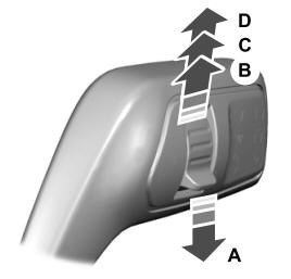
A - Single wipe.