Ford Explorer: Engine - 2.3L EcoBoost (201kW/273PS) / Removal and Installation - Timing Chain
Removal
NOTICE: Do not loosen or remove the crankshaft pulley bolt without first installing the special tools as instructed in this procedure. The crankshaft pulley and the crankshaft timing sprocket are not keyed to the crankshaft. The crankshaft, the crankshaft sprocket and the pulley are fitted together by friction. For that reason, the crankshaft sprocket is also unfastened if the pulley bolt is loosened. Before any repair requiring loosening or removal of the crankshaft pulley bolt, the crankshaft and camshafts must be locked in place by the special service tools, otherwise severe engine damage can occur.
NOTICE: During engine repair procedures, cleanliness is extremely important. Any foreign material, including any material created while cleaning gasket surfaces, that enters the oil passages, coolant passages or the oil pan can cause engine failure.
-
Remove the engine front cover.
Refer to: Engine Front Cover (303-01A Engine - 2.3L EcoBoost (201kW/273PS), Removal and Installation).
-
Remove the bolts and the timing chain tensioner.
.jpg) |
-
-
Remove the timing chain tensioner arm.
-
Remove the bolts and the timing chain guide.
-
Remove the timing chain.
-
Remove the timing chain tensioner arm.
.jpg) |
Installation
-
-
Install the timing chain.
-
Install the timing chain guide and the bolts.
Torque: 97 lb.in (11 Nm)
-
Install the timing chain tensioner arm.
-
Install the timing chain.
|
NOTE: If the timing chain tensioner plunger is not pinned in the compressed position, follow the next step.
-
Reset the timing chain tensioner.
-
Position the timing chain tensioner in a soft-jawed vise.
-
Spread the ends of the ratchet wire clip apart.
-
Using the soft-jawed vise, compress the plunger to the reset position.
-
Install a locking pin in the 2 holes of the timing chain tensioner body to hold the plunger in place.
-
Position the timing chain tensioner in a soft-jawed vise.
.jpg) |
-
NOTE: Do not remove the locking pin until the tensioner bolts are tightened.
-
Install the timing chain tensioner and the bolts.
Torque: 97 lb.in (11 Nm)
-
Remove the locking pin.
-
Install the timing chain tensioner and the bolts.
.jpg) |
-
NOTICE: Use an open-ended wrench on the flats of the camshaft to prevent the camshaft from turning.
If the intake VCT unit was removed, using an open-ended wrench, tighten the new exhaust VCT unit bolt.
Torque:
Stage 1: 26 lb.ft (35 Nm)
Stage 2: 135°
.jpg) |
-
NOTICE: Use an open-ended wrench on the flats of the camshaft to prevent the camshaft from turning.
If the exhaust VCT unit was removed, using an open-ended wrench, tighten the new exhaust VCT unit bolt.
Torque:
Stage 1: 26 lb.ft (35 Nm)
Stage 2: 135°
.jpg) |
-
Install the engine front cover.
Refer to: Engine Front Cover (303-01A Engine - 2.3L EcoBoost (201kW/273PS), Removal and Installation).
 Removal and Installation - Oil Pump
Special Tool(s) /
General Equipment
100-002
(TOOL-4201-C)
Holding Fixture with Dial Indicator Gauge
303-1685Alignment Tool, Camshaft
303-1688Preload Tool, Balance Shaft
3..
 Removal and Installation - Timing Chain Tensioner
Removal
NOTICE:
Do not loosen or remove the crankshaft pulley bolt without
first installing the special tools as instructed in this procedure. The
crankshaft pulley and the crankshaft timing spr..
Other information:
Ford Explorer 2020-2026 Owners Manual: General Information
The recommended tire inflation pressures are found on the Tire Label which is located on the B-pillar or the edge of the driver door. This information can also be found on the Safety Compliance Certification Label, affixed to either the door hinge pillar, door-latch post, or the door edge that meets the door-latch post, next to the driver’s seating position...
Ford Explorer 2020-2026 Service Manual: Removal and Installation - Manifold Absolute Pressure and Temperature (MAPT) Sensor
Materials Name Specification Motorcraft® Silicone Brake Caliper Grease and Dielectric CompoundXG-3-A ESE-M1C171-A Removal NOTE: Removal steps in this procedure may contain installation details. NOTICE: Do not pull the engine appearance cover forward or sideways to remove...
Categories
- Manuals Home
- 6th Generation Explorer Owners Manual
- 6th Generation Explorer Service Manual
- Body and Paint
- General Procedures - Brake Service Mode Activation and Deactivation
- Description and Operation - Identification Codes
- New on site
- Most important about car
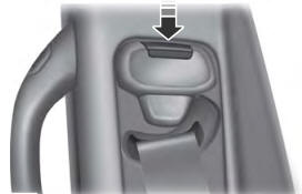
Seatbelt Height Adjustment
WARNING: Position the seatbelt height adjuster so that the seatbelt rests across the middle of your shoulder. Failure to adjust the seatbelt correctly could reduce its effectiveness and increase the risk of injury in a crash.