Ford Explorer: Supplemental Restraint System / Removal and Installation - Front Door Side Impact Sensor
Removal
.jpg) WARNING:
The following procedure prescribes critical repair steps
required for correct restraint system operation during a crash. Follow
all notes and steps carefully. Failure to follow step instructions may
result in incorrect operation of the restraint system and increases the
risk of serious personal injury or death in a crash.
WARNING:
The following procedure prescribes critical repair steps
required for correct restraint system operation during a crash. Follow
all notes and steps carefully. Failure to follow step instructions may
result in incorrect operation of the restraint system and increases the
risk of serious personal injury or death in a crash.
NOTE: LH (left hand) side shown, RH (right hand) similar.
NOTE: Removal steps in this procedure may contain installation details.
-
Refer to: Pyrotechnic Device Health and Safety Precautions (100-00 General Information, Description and Operation).
WARNING:
Before beginning any service procedure in this
manual, refer to health and safety warnings in section 100-00 General
Information. Failure to follow this instruction may result in serious
personal injury.
-
Depower the SRS.
Refer to: Supplemental Restraint System (SRS) Depowering (501-20 Supplemental Restraint System) .
-
Remove the front door trim panel.
Refer to: Front Door Trim Panel (501-05 Interior Trim and Ornamentation, Removal and Installation).
-
Remove the front door side impact sensor.
-
Disconnect the electrical connector.
-
Remove the bolts.
Torque: 22 lb.in (2.5 Nm)
-
Remove the front door side impact sensor.
-
Disconnect the electrical connector.
.jpg) |
Installation
-
NOTE: The front door side impact sensor mating surfaces must be smooth and allow for a flush attachment to each other.
To install, reverse the removal procedure.
-
Repower the SRS.
Refer to: Supplemental Restraint System (SRS) Repowering (501-20 Supplemental Restraint System) .
 Removal and Installation - Driver Knee Airbag
Removal
WARNING:
The following procedure prescribes critical repair steps
required for correct restraint system operation during a crash. Follow
all notes and steps carefully...
 Removal and Installation - Front Impact Severity Sensor
Removal
WARNING:
The following procedure prescribes critical repair steps
required for correct restraint system operation during a crash. Follow
all notes and steps carefully...
Other information:
Ford Explorer 2020-2024 Service Manual: Assembly - Engine
Special Tool(s) / General Equipment 100-002 (TOOL-4201-C) Holding Fixture with Dial Indicator Gauge 205-153 (T80T-4000-W) Handle 303-050 (T70P-6000) Lifting Bracket, Engine 303-096 (T74P-6150-A) Installer, Camshaft Front Oil SealTKIT-2009TC-F 303-103 (T74P-6375-A) Holding Tool, FlywheelT74P-77000-ATKIT-2009TC-F 303-1252Stretchy Belt Remover/ Inst..
Ford Explorer 2020-2024 Owners Manual: Settings
Press the button to enter the settings menu. Once you select a tile, press the button next to a menu item to view an explanation of the feature or setting. Sound Select this tile to adjust sound the settings. Clock Select this tile to adjust the clock settings...
Categories
- Manuals Home
- 6th Generation Explorer Owners Manual
- 6th Generation Explorer Service Manual
- General Procedures - Rear Camber Adjustment
- Using Tether Straps
- General Procedures - Transmission Fluid Drain and Refill
- New on site
- Most important about car
Windshield Wipers
 Push the lever up or down to operate
the windshield wipers.
Push the lever up or down to operate
the windshield wipers.
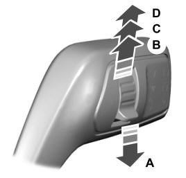
A - Single wipe.