Ford Explorer: Automatic Transmission - 10-Speed Automatic Transmission – 10R60 / Removal and Installation - Output Shaft Seal
Ford Explorer 2020-2024 Service Manual / Powertrain / Automatic Transmission / Automatic Transmission - 10-Speed Automatic Transmission – 10R60 / Removal and Installation - Output Shaft Seal
Special Tool(s) / General Equipment
.jpg) |
100-001
(T50T-100-A)
Slide Hammer |
.jpg) |
205-1018 Installation Tube |
.jpg) |
307-309 Remover, Torque Converter Seal TKIT-1994-FMH/FLMH TKIT-1994-LMH/MH TKIT-1994-FH |
.jpg) |
307-782 Installer, Output Shaft Seal |
| Punch | |
Removal
-
With the vehicle in NEUTRAL, position it on a hoist.
Refer to: Jacking and Lifting - Overview (100-02 Jacking and Lifting, Description and Operation).
Rear Wheel Drive (RWD) vehicles
-
Remove the rear driveshaft.
Refer to: Rear Driveshaft (205-01 Driveshaft, Removal and Installation).
-
Remove the stakes from the output shaft flange retaining nut.
Use the General Equipment: Punch
.jpg) |
-
Remove and discard the output shaft flange nut (7K440).
.jpg) |
-
-
Index mark the output shaft to the flange.
-
Remove the output shaft flange.
-
Index mark the output shaft to the flange.
.jpg) |
Four-Wheel Drive (4WD) vehicles
-
Remove the transfer case assembly.
Refer to: Transfer Case (307-07B Transfer Case, Removal).
All vehicles
-
Using the special tools, remove and discard the output shaft seal (7052).
Use Special Service Tool: 100-001 (T50T-100-A) Slide Hammer. , 307-309 Remover, Torque Converter Seal.
.jpg) |
Installation
-
Position a new output shaft seal on the special tools.
Use Special Service Tool: 205-1018 Installation Tube. , 307-782 Installer, Output Shaft Seal.
.jpg) |
-
Using the special tools, install the new output shaft seal.
Use Special Service Tool: 205-1018 Installation Tube. , 307-782 Installer, Output Shaft Seal.
.jpg) |
Four-Wheel Drive (4WD) vehicles
-
Install the transfer case assembly.
Refer to: Transfer Case (307-07B Transfer Case, Installation).
Rear Wheel Drive (RWD) vehicles
-
NOTE: If the output shaft or output shaft flange are replaced with new parts, align lazer applied ink marks.
Align the index marks made during removal.
.jpg) |
-
Install the new output shaft flange retaining nut.
Torque: 59 lb.ft (80 Nm)
.jpg) |
-
After installing the new output shaft flange
retaining nut, stake the slots to prevent it from coming loose.
Use the General Equipment: Punch
|
-
Install the rear driveshaft.
Refer to: Rear Driveshaft (205-01 Driveshaft, Removal and Installation).
All vehicles
-
Check the transmission fluid level.
Refer to: Transmission Fluid Level Check (307-01A Automatic Transmission - 10-Speed Automatic Transmission – 10R60, General Procedures).
 Removal and Installation - Main Control Valve Body
Removal
NOTE:
The Solenoid Body Strategy Data Download procedure must be performed if a new main control valve body is installed.
Remove the transmission fluid pan gasket and filter...
 Removal and Installation - Output Shaft Speed (OSS) Sensor
Removal
Remove the main control valve body.
Refer to: Main Control Valve Body (307-01B Automatic Transmission - 10-Speed Automatic Transmission – 10R80, Removal and Installation)...
Other information:
Ford Explorer 2020-2024 Service Manual: Description and Operation - Transmission Description - System Operation and Component Description
System Diagram Item Description 1 SSB 2 SSC 3 SSD 4 SSE 5 SSF 6 LPC 7 TSS 8 ISSB 9 Transmission 10 Transmission 11 TFT 12 TRS 13 SSA 14 PCM 15 TCC 16 OSS 17 ISSA 18 GSM 19 PBW Network Message Chart Broadcast Message Originating Module Message Purpose..
Ford Explorer 2020-2024 Owners Manual: Creating a MyKey
Use the touchscreen to create a MyKey: Insert the key you want to program into the ignition. If your vehicle has a push-button start, place the remote control into the backup slot. See Passive Anti-Theft System. Switch the ignition on. Access the main menu in the touchscreen and then scroll through the menus to change the settings of your MyKey...
Categories
- Manuals Home
- 6th Generation Explorer Owners Manual
- 6th Generation Explorer Service Manual
- Diagnosis and Testing - Parking Brake - Vehicles With: Electric Brake Booster
- Interior Trim and Ornamentation
- Engine
- New on site
- Most important about car
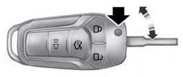
Integrated Keyhead Transmitter (If Equipped)
Use the key blade to start your vehicle and unlock or lock the driver door from outside your vehicle. The integrated keyhead transmitter functions as a programmed ignition key that operates all the locks and starts your vehicle, as well as a remote control.
Copyright © 2024 www.foexplorer.com